
This is a history of the development of the Talos missile. For greater detail and a broader consideration of early Navy missile development see references 4, 6 and 7. For detailed histories of the development of specific parts of the missile see the following pages:
History of the Talos missile ramjetHistory of the Talos missile booster
History of the Talos missile warhead
History of the Talos missile guidance and homing systems
History of the Talos missile aerodynamics and control systems
The Threat
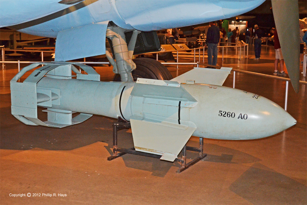
During World War II Germany, Japan and the United States were all trying to develop anti-ship missiles. The Germans produced several types of these weapons and were the first to put them to operational use. The Ruhrstahl PC 1400 X (Fritx-X) radio controlled armor-piercing glide bomb is an example of this early guided missile technology. It was developed from the 1400 kg SD1400 armor-piercing free fall bomb, with added wings and tail surfaces and a more aerodynamic nose. Movable fins in the tail could cause slight changes to the bomb's trajectory. It was launched from an airplane a few miles from the target. The bombardier in the plane watched a flare in the bomb's tail and guided the 3450 pound bomb to the target with radio signals. Later versions used wire guidance to avoid radio jamming. It had only about 20% accuracy against targets.
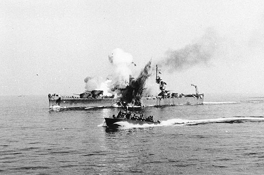
The fate of the USS Savannah CL-42 reveals the seriousness of the danger to shipping from these early anti-ship missiles. On September 11, 1943, the ship was supporting the Allied landing at Salerno Italy. During a German air raid a Dornier DO 217K-2 bomber flying at 18,500 feet guided a Fritx-X to strike the Savannah's Number 3 turret. The bomb penetrated the armored top of the turret and plunged through three decks to the lower handling room where it exploded. The blast blew a hole in the ship's hull and killed 197 men, including everyone in the turret and handling room. Effective damage control procedures saved the ship, but it was out of action for a year while being repaired.3 Numerous other ships were sunk by German glide and rocket-powered bombs launched from aircraft during the war, including large heavily armored battleships.
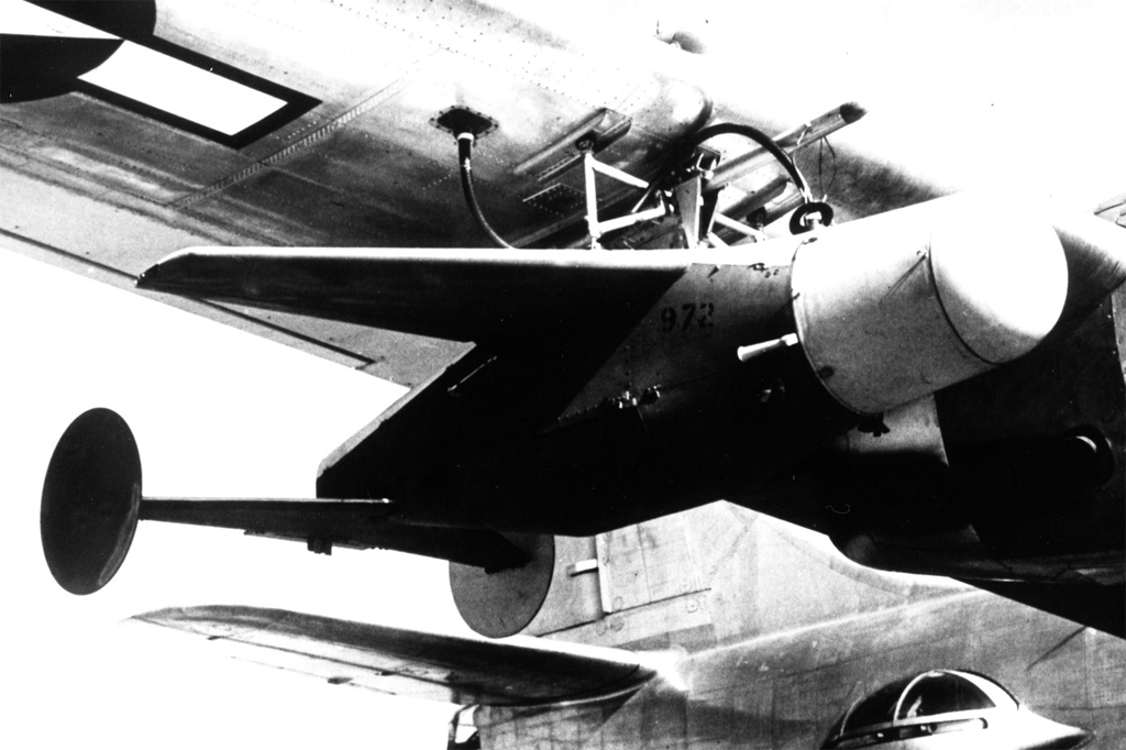
The US began development of an anti-ship guided missile in 1940.18 The program progressed through a series of test versions with different warheads and homing systems. The final version was a "fire and forget" radar guided missile, the SWOD-Mark 9 Mod 0 Bat radar guided anti-ship glide bomb that could deliver a 1000 pound warhead. It used a pulsed radar active homing system that had a transmitter and receiver in the missile. After it acquired the target it independently tracked its movements and adjusted course to intercept, closing the target with the speed of a fighter plane. This allowed the delivery aircraft to seek out another target or return to safety. It was primarily an anti-shipping weapon and was used to destroy many Japanese ships near the end of the war, including a destroyer that was sunk at a range of 20 miles. A version with modified radars was used against bridges in Burma.17 Bat was the first fully automatic guided missile to go into production by any of the combatants in World War II.18
These weapons were early guided missiles, and they posed a serious threat to naval and maritime shipping. Naval planners realized that anti-ship missile technology would develop rapidly and would become the most serious threat to the fleet. Some means was needed to intercept and destroy missile-carrying aircraft before they came close enough to launch their weapons.
In July 1944 the Navy Bureau of Ordnance (BuOrd) began an initial analysis and evaluation of the problem of protecting a task force from guided missiles launched from enemy planes beyond the range of existing anti-aircraft guns and fire control systems. The report recommended immediate effort to develop a guided jet-propelled antiaircraft missile, preferably supersonic. The initial plan was for a 2000 pound missile that flew at 1850 ft./sec. (1261 mph). It would be launched by a 2000 lb rocket and propelled by a ramjet sustainer with a maximum flight time of 63 seconds and a maximum range of 38,800 yards (22 miles). It was assumed that the target would be at 10,000 feet altitude and would be intercepted at 20,000 yards (11.4 miles).1
In the fall of 1944 BuOrd requested advice about defensive weapons for ships. Johns Hopkins University Applied Physics Laboratory (APL) produced an analysis of the problem that revealed that the missile would have to be supersonic to be able to reach a target before it would be close enough to launch an anti-ship missile. Aircraft, even jets, were subsonic at that time, and were too slow. Existing rockets could not travel the required distances. Ramjets were thought to be theoretically capable of meeting the requirements but a practical ramjet had never been tested. APL proposed a supersonic ramjet-propelled missile with a range of 20,000 yards (11 miles) that would carry a 600 pound warhead. It would use radar guidance and some form of homing system to steer it to the target. They estimated that a prototype could be built in two years, with limited use in the later stages of the war (it was assumed that the war would last into 1946 or 1947).
While these discussions were in progress the Japanese introduced the kamikaze in October 1944. This was another type of guided missile, and they caused great damage to the fleet, sinking about 50 Navy and merchant ships. The damage being inflicted by these weapons gave extra importance to the development of an anti-aircraft guided missile. In December 1944 BuOrd decided to proceed with development on an "urgent" basis.4, 6
Bumblebee

In 1940 a project was started by Merle Tuve of the Carnegie Institution to develop a radio proximity "VT" (variable time) fuze for anti-aircraft shells. The group was designated Section T (Tuve's initial). To speed development in 1942 a contract was signed with Johns Hopkins University to organize the Applied Physics Laboratory (APL) to pursue work on the fuze. The fuze was in production and delivered to the fleet by the end of 1942. The first successful use of the new fuze was in January 1943 when the USS Helena used it to shoot down Japanese aircraft.5
After the VT fuze project was completed APL turned its attentions to the development of a guided missile to intercept aircraft beyond the range of gunfire. On December 1, 1944, APL began a new research contract with BuOrd to proceed with the development of guided jet propelled missiles, and all other Bureaus of the Navy were to provide support as needed. The Central Laboratory for Section T was restructured as an entity directly under contract to BuOrd, to operate independently as the Applied Physics Laboratory. The purpose of "Task F" was to produce a prototype interceptor missile, or prove that it couldn't be done. The proposed missile was given the code name Torch (the "T" from Section T).4
In Early 1945 the code word "Bumblebee" was assigned. The name came from a wall hanging Dr. Tuve noticed in the Office of Scientific Research and Development:
According to recognized aerotechnical tests,
the bumblebee cannot fly because of the
shape and weight of his body in relation
to the total wing area.
BUT, the bumblebee doesn't know this,
so he goes ahead and flies anyway.
The similarity to the work of Task F was noted, and the project name "Bumblebee" seemed appropriate.6
When work started on Task F to determine if a ramjet missile would work some thought was given to the name of the new missile. Bulfinch's Age of Fable described the demigod Talos that flew through the air at such great speeds that he turned red hot, and destroyed his enemies by grabbing them and pressing them to his breast to incinerate them. The name was adopted for the new missile in January, 1948.4
Initial work was focused on general elements of the problem without emphasis on a specific design. The problems investigated were thrust to drag ratio for ramjets, supersonic control methods, aerodynamic drag at supersonic speeds, and whether operation at supersonic speeds presented unknown problems or limitations. The intent was to have answers by January 1946. The ramjet engine, radar guidance and large booster rockets did not exist when the overall design was created, and at least five years were anticipated to develop a tactical missile.1
The project was broken down into several parts:
1. Burner: Investigate stationary ramjet operation in wind tunnels to determine thrust and experiment with fuels.
2. Aerodynamics: Study supersonic drag, stability and control problems using wind tunnels and free flight experiments.
3. Models: Build and fly ramjet supersonic models and obtain data on thrust and drag with radio telemetry, radar tracking and photographic tracking.
4. Guidance and Control: Develop systems for guidance, control, stabilization and target tracking.
5. Facilities: Develop test fields and observation facilities, plus laboratories and wind tunnel facilities.
6. Launching: Develop and study launching methods.
No facilities existed in January 1945 for testing supersonic ramjets. An abandoned Coast Guard Station at Island Beach, New Jersey, was hastily developed into a field test site. By April the Bumblebee team was firing test vehicles off the New Jersey shore. A truck mounted SCR-584 radar was used to track the test vehicles. Tests were complicated by off shore shipping and fishing boat traffic, requiring firing to be delayed until the range was clear.
A ramjet engine test facility was constructed at Silver Spring, Maryland. Three large air compressors were discovered at Shasta Dam, California, that had been used to drive pneumatic hammers during construction of the dam. These were moved to Silver Spring to generate airflow for a new supersonic wind tunnel. By July 1945 experiments were underway to test ramjet engine models and fuels.
At the same time the Navy was revamping a vacated factory in Daingerfield, Texas. A 100,000 cubic foot per minute blower for a blast furnace was converted to drive a 10 foot diameter, 125 foot long high altitude wind tunnel large enough to test prototype missile designs. The new Ordnance Aerophysics Laboratory was in operation by November 1945, testing 19- and 21-inch ramjet models. It operated at wind speeds between Mach 1.75 and Mach 2.75 and could simulate sea level flight at 2000 mph.6
As test vehicles became larger and flew to greater distances the flight program was moved from New Jersey to a more remote area at Camp Davis North Carolina. As ranges increased further the program was moved to the Naval Ordnance Test Station at Inyokern California (China Lake). Further tests of long range intercepts were conducted at White Sands New Mexico.
The initial goals for the Bumblebee Project were to develop a missile that could intercept a target at a horizontal range of 10 miles and 30,000 feet altitude, with an accuracy of 2 feet per 100 feet target range. A warhead weight of 300-600 pounds was required for a kill probability of 0.3 to 0.6. Powered flight up to intercept was another goal.4
Early efforts were concerned with studying the basic problems associated with the goal of producing a supersonic missile. One group was developing burner test vehicles (BTV) to study ramjet performance. A series of increasingly large and complex test vehicles was designed and flown to evaluate ramjet performance. The Ramjet History page provides a detailed history of the development of the Talos ramjet engine. Knowledge about ramjets learned in the Talos program helped with the design of ramjets for the XB-70 supersonic bomber and the SR-71 reconnaissance plane.
Another problem was the production and testing of large booster rockets. These had to be ten times larger than anything existing. The Talos Booster History page describes the problems and solutions during booster development. Lessons learned from the Talos booster development project paved the way for future large solid fuel booster rockets for ICBMs, satellite launch vehicles and the space shuttle.
Another phase of the project concentrated upon creating a more effective warhead for the missile to allow high kill probabilities at greater ranges than possible with the warhead types in use in World War II. The Warhead History page describes this effort.
A large effort was begun to develop telemetry methods to return data from experimental test vehicles. Suitable methods were nonexistent at the beginning of the project, and the telemetry project was as much of a design effort as any other part of Project Bumblebee. It was necessary to monitor the missile in flight to measure its performance and provide information in case something didn't work right. A simple "wireless" system was developed to allow transmission of pulsed or modulated tones that could be translated into useful information. Early telemetry systems were built with VT fuze components and the new sub-miniature vacuum tubes. Four to eight FM carriers were transmitted at 60 to 80 MHz and later 200 MHz. Early data recordings were on phonograph-record-like disks. Paper strip visual recordings of oscilloscope displays were also used. Later the newly developed magnetic tape recording was used. The early Bumblebee telemetry system was eventually developed into the common helical antenna that became the standard FM/FM US telemetry system.6
While experiments were proceeding with ramjet missile development entirely different smaller subsonic test vehicles were developed for initial tests of the beamriding scheme. These initial beamriding test vehicles were relatively simple short range rockets using existing technology to allow an early start on testing guidance systems. The Guidance and Homing History page provides details of the development effort.
The beam riding scheme that was devised had two phases. Initial launch was into a wide capture beam. The missile maneuvered to the center of this beam, and then the beam was narrowed to a thin guidance beam to direct the missile to the target. An antenna in the tail of the missile detected the guidance beam. Position information in the beam was decoded and converted to wing control commands to steer the missile into the center of the beam. This had never been tried before and a lot of experimentation was needed to design and test various ideas. As the missile range increased the diameter of the guidance beam broadened, reducing accuracy of the beam rider method. At ranges of twenty miles and more the guidance error was too great to ensure a high probability of destroying a target.6
Supersonic test vehicles (STV) were designed to test steering and control during supersonic flight. These were more advanced two stage rocket powered test vehicles that incorporated the beamriding guidance systems developed with the smaller subsonic beamrider test vehicles. The STV-3 test vehicle was the most complex of the solid rocket powered vehicles. It was launched by a solid rocket booster and had a small solid rocket sustainer to propel it at supersonic speeds to a range of about ten miles.
In 1948 the STV-3 was recognized as having potential as a short range antiaircraft missile that would meet most of the initial Bumblebee goals if the telemetry section was replaced with a warhead. This missile could be operational before Talos and would give the fleet greater anti aircraft capability than existing guns. A decision was made to proceed with a separate program to develop a prototype missile and it was given the name "Terrier." This was the progenitor of the modern Standard missile used with the current Aegis missile system.
Extending the range
Since the proposed Terrier missile could intercept short range targets the goal for Bumblebee was extended to 50 miles and a requirement for terminal guidance was added. This change of plans caused substantial rework of the design and added some delay in the development of the missile.
Initial plans were for Talos to use beamriding for midcourse guidance after it separated from the booster rocket. It was thought that the missile could ride the target tracking radar beam to the target. However, as range increased the diameter of the guidance beam became greater, allowing the missile to wander farther from the beam center. This meant that the distance from the target at intercept became greater with increasing range, and at distances of more than 10 miles kill probability was unacceptably low.10
To meet the longer range goal a separate guidance radar beam was necessary. A tracking radar provided information on the direction to the target and the guidance radar generated the beam for the missile to follow. This beam carried information that allowed the missile to determine its position within the beam and steer to the beam center. By controlling beam position the ship guided the missile to the vicinity of the target. This scheme had an additional benefit that several missiles could be guided to a target along one guidance beam.10
Early tests showed that the missile would consume too much fuel if it flew direct line of sight to a long range target at low altitudes where air density was greatest. It was decided to use the beamriding beam to direct the missile to high altitudes where it operated more efficiently in thinner air and then direct it to a point of intercept where it would dive on the target.
A terminal guidance method was needed, and a semiactive radar homing (SARH) seeker was chosen. At the end of the midcourse beamriding phase the ship sent a signal to the missile to arm the warhead and activate the homing system. The launching ship illuminated the target with a homing signal that reflected from the target. The missile's seeker detected the reflected signal which guided the missile to the target. This gave a terminal homing system with high accuracy that was not affected by the distance from the ship to the target.
The design of the ramjet missile with the large air intake opening at the front posed a problem. The common way to implement a radar seeker was to use a steerable parabolic antenna to detect the homing signal, but this would interfere with the operation of the air intake. An interferometer-type antenna was chosen for several reasons. It used four small widely spaced antennas that could be mounted around the air intake and would not interfere with ramjet operation. These antennas were much smaller and simpler mechanically than a gimbal-mounted scanning dish antenna. This arrangement had a very wide target acquisition aperture and would allow rapid target acquisition without having to provide the missile with information about the direction to target.10
A supersonic Experimental Prototype Missile (XPM) design was created that had all the necessary functions of an antiaircraft missile. This was to have the initial Talos missile airframe and would combine the prototype engine, fuel, control, guidance, homing and warhead systems that came out of the test and development programs. This test vehicle eventually became the operational Talos missile.
Talos Evolution
| Name | Designation | Alternate | Mk/Mod | Function | Warhead | Date |
|---|---|---|---|---|---|---|
| Burner Test Vehicle | 6" BTV | Burner tests | None | 1945 | ||
| Burner Test Vehicle | 10" BTV | Burner tests | None | 1945 | ||
| Ramjet Test Vehicle | 18" RTV | Burner tests | None | 1945 | ||
| Cobra | 6" BTV | Model 3B | Burner tests | None | 1946 | |
| Burner Test Vehicle | 18" BTV | PTV-N-4 | Burner and control tests | None | 1947 | |
| Experimental Prototype Missile | XPM | RTV-N-6 | Prototype missile | Fragment | 1949 | |
| Prototype Talos | XSAM-N-6 | Prototype Talos | Fragment | 1951 | ||
| First Tactical Talos | RIM-8A | SAM-N-6b | Mk 11 Mod 0 | Surface-to-air | Fragment | 1952 |
| Prototype Talos W | XSAM-N-6W | Prototype Talos nuclear | W30 | 1953 | ||
| First Tactical Talos nuclear | RIM-8B | SAM-N-6bW | Mk 11 Mod 1 | Surface-to-air nuclear | W30 | 1954 |
| Extended Range Talos | RIM-8C | SAM-N-6b1 | Mk 11 Mod 2 | Surface-to-air Surface-to-surface | CR | 1956 |
| Extended Range Talos nuclear | RIM-8D | SAM-N-6bW1 | Mk 11 Mod 4 | Surface-to-air nuclear | W30 | 1956 |
| Prototype Unified Talos | XSAM-N-6c1 | Experimental Unified Talos | CR/W30 | 1959 | ||
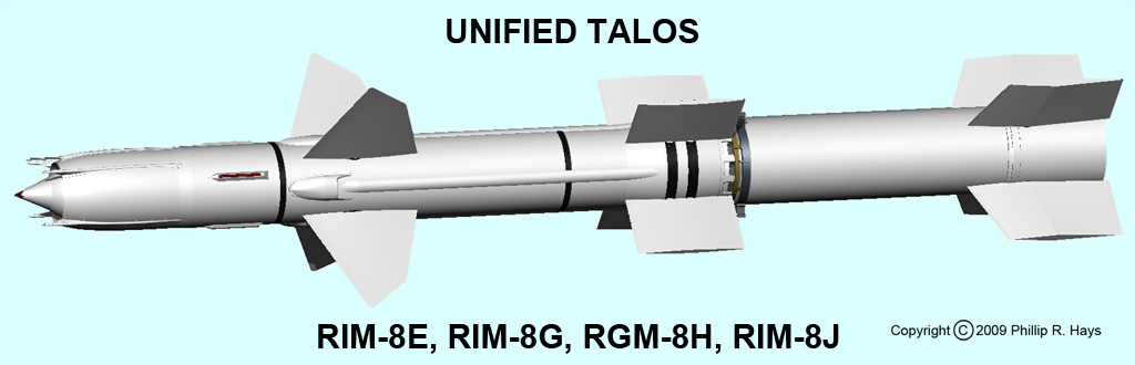
| Unified Talos | RIM-8E | SAM-N-6c1 | Mk 11 Mod 5 | Surface-to-air Surface-to-surface | CR/W30 | 1960 |
| Talos | RIM-8F | SAM-N-6b1(CW) | RIM-8C with RIM-8E seeker | CR | ||
| Talos | RIM-8G | Surface-to-air Surface-to-surface | CR/W30 | 1966 | ||
| Talos ARM | RIM-8H | RGM-8H | Anti-radiation missile | CR | 1968 | |
| Talos | RIM-8J | Surface-to-air Surface-to-surface | CR/W30 | 1971 | ||
| Talos LAST | XBQM-8D-1 | Non recoverable target | None | 1973 | ||
| Talos LAST | XBQM-8F-1 | Recoverable target | None | 1973 | ||
| Vandal | MQM-8G | High speed target | None | 1983 | ||
| Vandal Extended Range | MQM-8G-ER | High speed target | None | |||
| Vandal Extended Extended Range | MQM-8G-EER | High speed target | None |
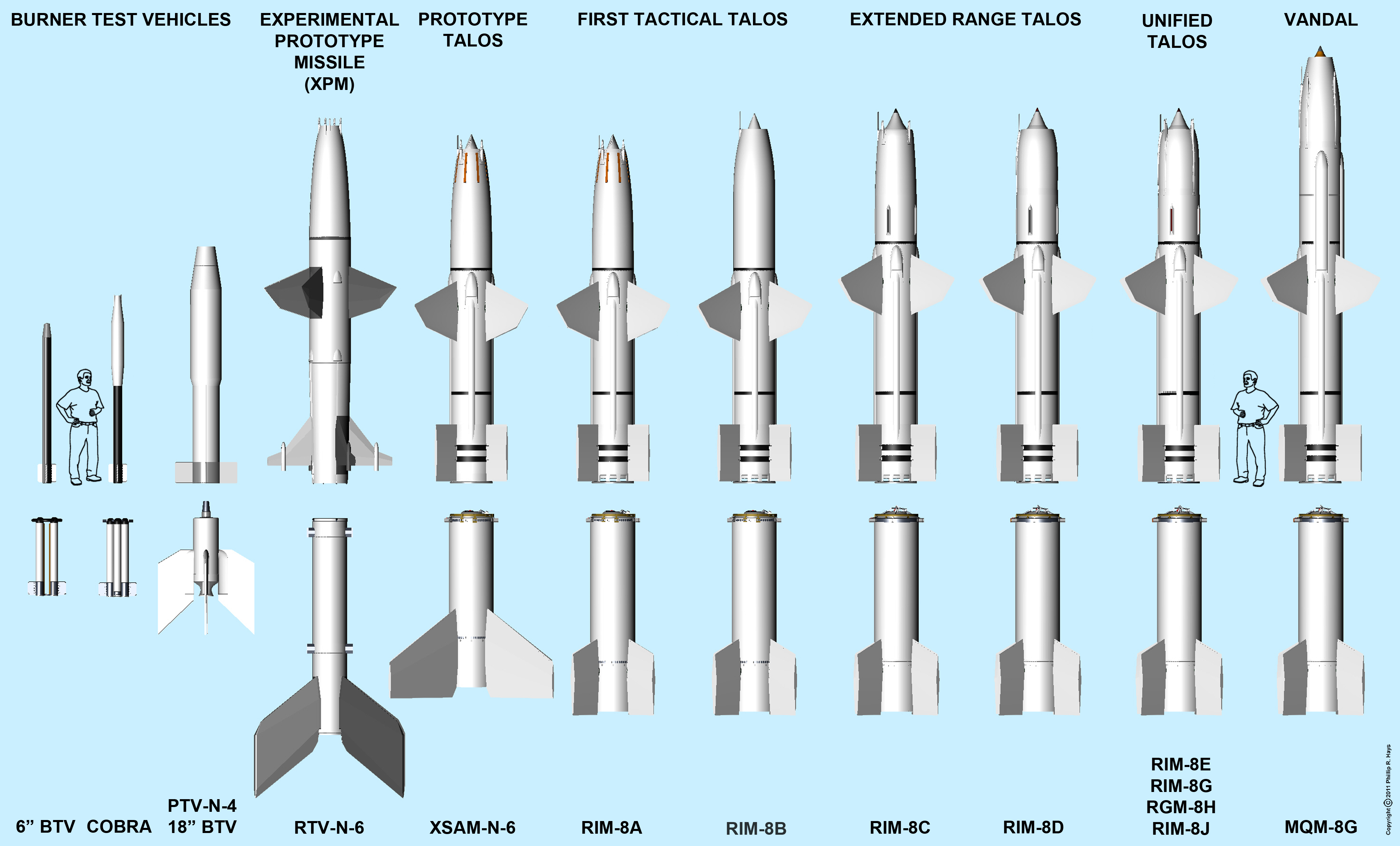
Early Test Vehicles
In February 1945 flight tests were begun with 6 inch diameter Burner Text Vehicles (BTV) launched with solid rocket boosters. The boosters were clusters of four or six 5-inch HVAR model 38 "Holy Moses" aircraft rockets that were in use in the war. The warheads were removed and the rockets were ducted together with automobile exhaust pipe in an effort to achieve equal combustion chamber pressure (equal thrust) in all the rockets.
The first tests were simple dummy rounds that were used to develop the solid rocket boosters for propelling the BTVs to supersonic speeds. On 24 April, 1945, the first sustained thrust was achieved in a flight test vehicle. The first clearly successful test producing thrust at supersonic speeds was on 13 June 1945. The vehicle flew at 1750 feet per second (1200 mph) for 10,000 yards. The first demonstration of thrust in excess of drag was in October 1945.13 These early tests were unguided projectiles fired over the ocean.
In late 1945 an 18 inch diameter Ramjet Test Vehicle (RTV) was built. It was designed to carry guidance equipment and a warhead. It was a failure because it was unable to withstand the stresses during flight.
The initial 6 inch BTV design was modified in early 1946 with a forward section expanded to 8.5 inch diameter to provide more space for fuel, instruments and telemetry systems. The modified Model 3B BTV was called Cobra because of the wider front end. It weighed 70 pounds and developed between 2000 and 3000 horsepower, equivalent to a large radial airplane engine.
Another 18-inch diameter burner test vehicle with warhead and guidance equipment similar to the RTV was produced in 1947. It was a scaled up Cobra that used kerosene fuel and cruised at Mach 2.4 at 30,000 feet altitude. It demonstrated throttleability, ability to accelerate after boost (from Mach 2.0 to 2.4), and had a cruise range of 10 miles.8 This was called the PTV-4 or PTV-N-4 Burner Test Vehicle (BTV) and it was used for additional tests of the ramjet engine.
The design for a larger Experimental Prototype Missile (XPM) was started in late 1946. It had a body diameter of 28 inches with a combustion chamber 24 inches diameter. The XPM (RTV-N-6a4a) first flew in March 1949. This was the first full sized test configuration combining all of the prototype systems developed in the earlier test vehicles. It flew at Mach 2 at 30,000 feet and had a range of 25 nautical miles. In 1951 the first target kill was achieved when an XPM beamrider collided with a target drone. In October 1952 an XPM intercepted a drone at White Sands, proving the operation of the homing system.6 Several variations of this missile and booster were flown during flight testing.
In 1951 development began on the XSAM-N-6, the prototype Talos missile. It was the first full sized Talos missile and had a range of 50 nautical miles. It lead to the development of the First Tactical Talos SAM-N-6b in 1955. Numerous problems arose during the testing of this missile and several modifications were made to solve them. The most visible difference between the prototype and the First Tactical Talos missiles were the openings that were made around the exhaust nozzle to allow air to flow through the missile during launch phase. This prevented "organ pipe" oscillations in the air column in the missile. These vibrations in the prototype missiles were severe enough to cause equipment failures that destroyed the missile. The short prototype booster with the large fins was replaced with a longer and more powerful booster in the production models.
Talos W Design
In parallel with the development of the Talos airframe and engine work the guidance and homing systems were being designed and tested. The interferometer homing system was tested in many ways, including stationary installations on the ground with aircraft flying overhead and mobile test platforms on trucks and test aircraft.
While testing the prototype homing systems a significant fault was discovered. If multiple targets were a few hundred feet apart the missile's homing system could fail to pick a single target and have a large miss distance. This made the missile vulnerable to simple tactics if an enemy knew the critical distance.4
In 1951 development began on a small nuclear weapon to be carried by fighter-bomber aircraft. It had a smaller diameter than the Talos missile so it seemed ideal for adaptation as a missile warhead. Talos W would be guided to the target with the beamrider system and detonated on command from the ship. At maximum range beamriding was inaccurate and required a kill radius of 1000 to 2000 feet. The nuclear warhead would produce sufficient "gust loading" to achieve a kill at longest range to target, but overpressure and thermal effects would also cause damage.4
The nuclear warhead required a longer missile and moved the center of gravity forward. As a result the missile was more stable than the conventional version but not as maneuverable. This was not a problem for the nuclear armed missile because it did not have to get as close to the target to achieve a kill.4 The first prototype W missile was tested in 1953, 18 months after the design was started.
First Tactical Talos RIM-8A (SAM-N-6b) and RIM-8B (SAM-N-6bW)
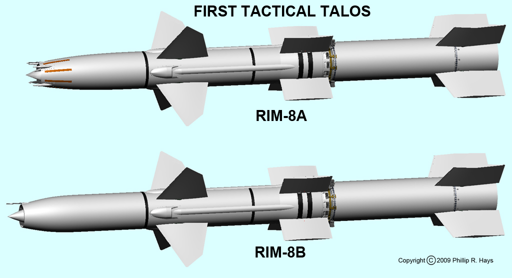
This was the first version of the Talos missile. It carried a conventional fragmentation rod warhead in an annular space in the missile nose surrounding the ramjet tube, behind a small compressor innerbody. The nuclear warhead was much larger than the conventional warhead and was housed in a larger innerbody that served as the intake compressor. The RIM-8B nuclear missile was longer than the conventional RIM-8A missile. The homing interferometer antennas were removed from the nuclear version along with the associated homing electronics.
The conventional version used a seeker that homed on the reflected pulse mode tracking radar signal.4 This system worked well against mid to high altitude targets and the majority of intercepts produced skin-to-skin contact with the target. But with low altitude targets the tracking radar illuminated surface objects causing many false signals that hid the target.10 The missile did have effective home on jam capabilities.
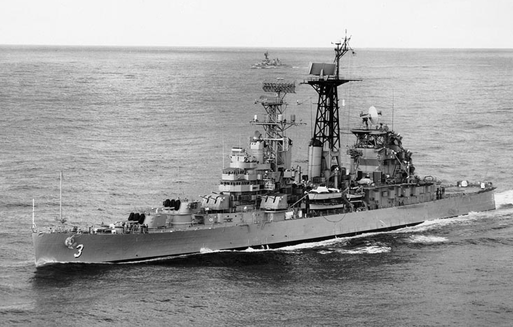
Initial First Tactical Talos missile (SAM-N-6b) was flown in 1952. Introduction into the fleet was delayed by lengthy ship conversions, and the missile was finally deployed on the USS Galveston CLG-3 in 1958.
Extended Range Talos RIM-8C (SAM-N-6b1) and RIM-8D (SAM-N-6bW1)

Development of a longer range missile was started in 1953, partly in response to Air Force interest in using Talos to defend Strategic Air Command air bases. The range was extended from 50 to 100 miles and altitude ceiling was increased from 60,000 feet to 70,000 feet. The Talos ER missile was first flown in 1961.
The new design was more efficient, having greater maneuverability, lower maneuver-induced drag and greater thrust. It could engage faster and more maneuverable targets. Flight speed at high altitudes was increased from 2000 to 2400 feet per second (1600 mph). The missile tail fin span was increased to improve aerodynamic characteristics. The fuel tank was lengthened to give 20% greater capacity. The combustion chamber was lengthened 6 inches for better high altitude combustion efficiency. The engine inlet was redesigned to a double cone to improve thrust at high altitudes. The booster was made larger to give an adequate launch speed for the heavier missile.4
Extended Range Talos had separate optimized capabilities for the two versions. The original homing electronics required more space than was available in the nuclear version. New compact electronics were developed for the Talos W for beamriding, control system and beacon transponder, and these were eventually integrated into the conventional version.
A new continuous wave (CW) seeker was developed that used the Doppler effect to discriminate between low altitude targets and background clutter. The ship computed the closing rate of the missile and target and transmitted Doppler shift information to the missile in the tracking radar beam to improve target acquisition times. Homing was activated about ten seconds before intercept and the missile acquired the target in two seconds or less. The new seeker electronics were essentially immune to jamming, and could distinguish between multiple jamming sources and home on the closest.
The new CW guidance system was effective against surface ship targets even though the Doppler shift was the same for the ship and the ocean. Several improvements to the electronics increased the signal to clutter ratio sufficiently for the missile to identify the target. The missile was launched at a high angle as in anti-air mode and was guided over the target where it dove almost straight down. Maximum range depended upon the capability of the ship to track and illuminate the target, but the missile could intercept ship targets beyond the radar horizon and even in the presence of land clutter. Because of the large size of the missile and the high intercept speed Talos caused enormous damage to target ships.10
Unified Talos RIM-8E (SAM-N-6c1)
The two missile types (conventional and nuclear) caused logistical problems and required shipboard stowage of missiles that were useless in a non-nuclear war. The 6b missiles also had limited effectiveness against low flying targets because of sea clutter. The solution was to design a missile with interchangeable warheads.3, 13
The Mk 46 high explosive continuous rod warhead was developed to fit into the same innerbody as the W-30 nuclear warhead. A new solid state (transistorized) continuous wave interferometer seeker was developed in 1956 to allow low altitude intercepts. This seeker was used by conventionally armed missiles to home on the target. Homing system electronics were miniaturized and packaged to fit in the space in the nuclear missile. The 6c1 was essentially a modified 6bW1 airframe with interchangeable warheads and a miniaturized CW seeker. The electronics were repackaged as modules that were easily replaced. This allowed for future variations simply by exchanging modules in the 6c1 airframe.4
The system had a shore mode for attacking large surface targets or shore targets. It would guide a beamriding nuclear armed missile to the target and detonate the warhead on command. The range was limited by the desired airburst altitude and the line of sight from the ship. Targets could be engaged at a range up to 40 miles.14
Flight testing started in June 1959 and production missiles were available for the fleet in the early 1960s.
A modified version of the RIM-8D with a CW seeker was called RIM-8F. A modified RIM-8E with improved guidance and antiship capability was called RIM-8G.4
| RIM-8E/G/H/J | Missile | Booster |
|---|---|---|
| Length (inches) | 254 | 134 |
| Diameter (inches) | 28 | 30 |
| Wing span (inches) | 107 | |
| Fin span (inches) | 74 | 77 |
| Weight (pounds) | 3360 | 4360 |
Notes:
1. Booster body length was 132 inches, but the fins extended 2.3 inches behind the body.
2. Missile wing span is often given as 110 inches. This would be the span if the tip was pointed (where the two straight edges would meet). However, the tip is filleted, reducing the span to 106.946 inches.
3. Missile fin span is sometimes listed as 82 inches and booster fin span as 72 inches. A quick look at a photo reveals that the spans are almost the same. Some drawings give the dimensions listed above, and a comparison of fin span to body diameter in photos supports these dimensions.
Talos Antiradiation Missile RIM/RGM-8H
The VietNam war made evident the need for an antiradiation missile (ARM) to destroy enemy radars. Work began in 1965 to create a passive homing missile that would seek out radar installations. The new missile was tested in 1967 at White Sands and on ships in 1968. It had a 120 nautical mile range. It was first deployed on the USS Long Beach CGN-9 and then to other ships in the fleet.4
The ship directed the missile to the vicinity of the target using beamrider midcourse guidance. When the missile was in the target area the ARM homing system was activated and started looking for emissions from the radar. The missile was directed to dive toward a point about four miles beyond the expected target position. It used a look-down search mode that rejected signals from more distant radars. It looked for the appropriate rate of change for the line of sight to the target. When the target was accepted the missile either dove at a 45° angle to the target or passed over and dove straight down.10
Flight tests at White Sands Missile Range produced many direct hits against radar targets. The missile was deployed to ships in the Gulf of Tonkin and was used successfully against radars in North Vietnam. In February 1972 the USS Oklahoma City was the first ship to destroy a surface target in combat with Talos ARM.
Long Range Talos RIM-8J
This was essentially a modified RIM-8G that used higher energy JP-4 dimer fuel to achieve a 130 nautical mile range. This was a higher density fuel that packed more energy in a given volume than the original JP-5 fuel. The 8J had an improved seeker, electronic counter-countermeasures, chaff rejection, multiple target discrimination and low altitude fuzing.4
The original CW seeker was susceptible to some types of deception measures. A new homing system was developed in the mid 1960s that was immune to any conceivable jamming, even if the designer of the jamming equipment was familiar with the Talos electronics. Twenty-five flight tests were conducted against single and multiple jammers. Examination of the results showed that the new seeker had a higher kill probability against jamming targets than against non-jamming targets. In one test the missile homed on an airborne jammer, but since it didn't have a warhead it passed close by the airplane without exploding and then locked on to another land based jammer and homed on it. This new system was introduced in 1971.10
Talos LAST
In June 1972 the Army Missile Command contracted Bendix Aerospace Systems to modify obsolete Talos missiles into low altitude supersonic drones. This was the Low Altitude Supersonic Target (LAST) program to produce targets for developing Army SAM-D and Navy Aegis missile programs.12
Two types of drones were to be produced from RIM-8D and RIM-8F Talos missiles that had been removed from service, a recoverable XBQM-8F-1 and non-recoverable XBQM-8D-1. Both drones would use the same internal guidance systems. Vertical control used a radar altimeter and horizontal (steering) control used an off the shelf AN/DRW-29 command receiver. A new digital to analog converter was added to the existing Talos autopilot to generate roll control and turn error signals for wing position control. A self-destruct package was installed in the drones.
Missiles were controlled by computer programs at White Sands and by manual joystick remote control at the Pacific Missile Range. After booster separation the drones flew either a high altitude trajectory at 10,000 feet or a low altitude trajectory at 250-500 feet. The range was 20 to 24 nautical miles. At the end of the flight the 8F missiles flew to an altitude suitable for parachute deployment. A chute was released from a forward compartment in the missile and it descended at 25 feet per second to the surface for recovery. Only 16 8D and 24 8F missiles were available after the developmental tests, and the parachute recovery system was used to allow the 8Fs to be reused.
Nine development flights (three 8Ds and six 8Fs) were flown between June 1973 and April 1974, five at White Sands and four were launched from San Nicholas Island at the Pacific Missile Range. Conversion of the remaining missiles started in 1974 and operational targets were available in 1975.
Vandal
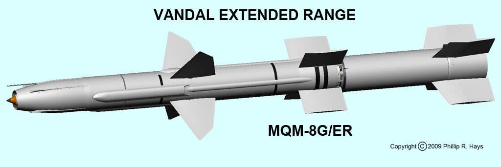
In the late 1970s the remaining Talos ships participated in BUZZARDEX operations where Talos missiles (Buzzards) were launched as supersonic targets for other ships and aircraft. Plans were underway in 1977 to convert operational Talos missiles to supersonic target drones. After the USS Oklahoma City CG-5 was decommissioned in 1979 the remaining Talos missiles were converted to Vandal supersonic targets and redesignated MQM-8G.
Changes to the electronics package and air intake allowed the missile to fly supersonic at very low altitudes to simulate anti-ship missiles. Additional fuel was added and a new autonomous guidance system was installed. Vandals were four feet longer and 490 pounds heavier than the Talos missiles. They cruised at Mach 2.2 at sea level with a range of 43.5 miles.7
Later modifications produced the MQM-8X Fleet Vandal, MQM-8G/ER Extended Range Vandal and the MQM-8G/EER Extended Extended Range Vandal. The EER version carried an autonomous GPS guidance system allowing the missile to maneuver without ground based guidance.15
The Vandals were fired from Mk 7 launchers that were removed from decommissioned Talos ships. The launchers were installed at land bases and on barges. Launch sites were at White Sands, New Mexico, Wallops Island, Virginia, Barking Sands, Kauai, Hawaii and San Nicholas Island, California. The first Vandal shots were conducted in 1983. The last of 644 Vandal targets was flown in 2005 when the supply of missiles was exhausted.9
Talos ships
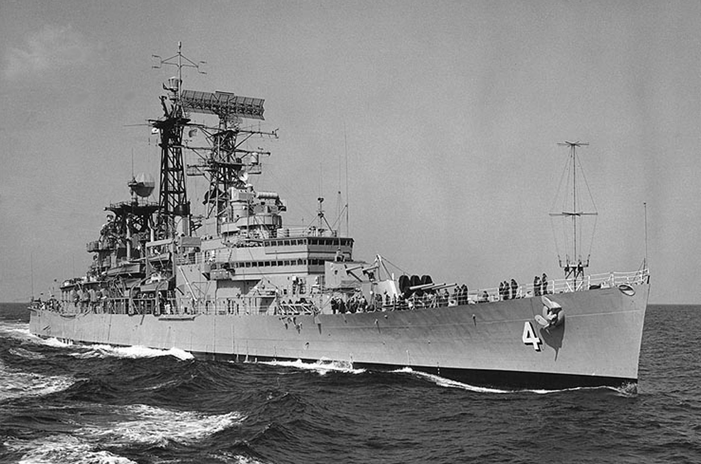
The USS Galveston CLG-3 was the first ship to carry the Talos missile. The ship was completed after World War II as a Cleveland class light cruiser but was never commissioned. It was converted to carry Talos and commissioned as CLG-3 on 28 May 1958. The ship was rushed through conversion, with no significant changes forward, so it could serve as a test bed for the new Talos systems. On 24 Feb 1959 the ship conducted the first Talos missile shot at sea. The Galveston suffered badly from hogging and was decommissioned on 25 May 1970.
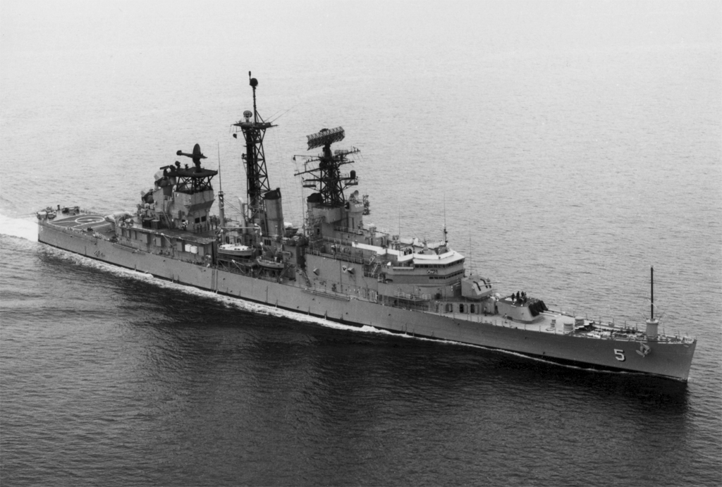
The USS Little Rock CLG-4 was the second Talos ship. Another converted Cleveland class cruiser, she had extensive alterations forward to provide space for a fleet flagship. She was commissioned on 3 June 1960 and decommissioned 22 November 1976 after serving as flagship for the Second and Sixth Fleets. The first ship launched Talos missile to destroy a drone was fired from the USS Little Rock on October 21, 1960.
USS Oklahoma City CLG-5 was commissioned 7 September 1960 and decommissioned 15 December 1979, after serving the longest of any Cleveland class ship. The ship had fleet flagship accommodations and served as flagship for the First and Seventh Fleets. In February 1972 the Oklahoma City destroyed a North Vietnamese mobile radar site with a Talos ARM missile. It was the first successful combat surface to surface missile operation in US Navy history. On 6 November 1979 the USS Oklahoma City fired the last Talos missile launched from a ship.
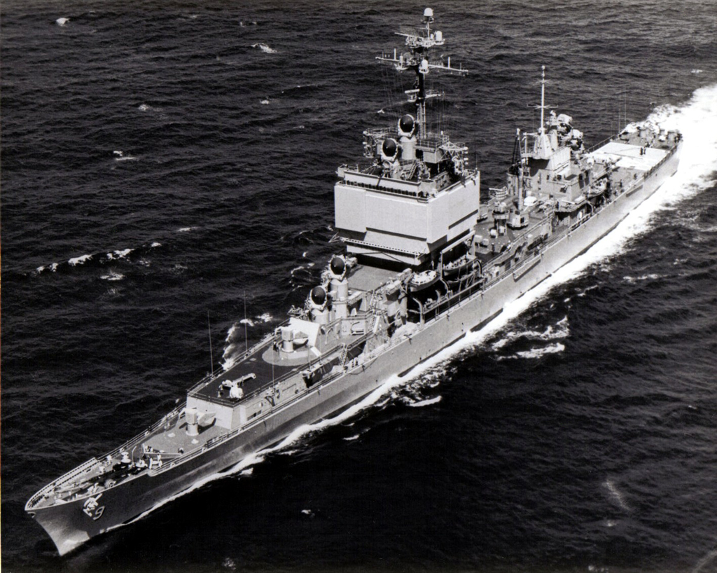
USS Long Beach CGN-9 was the first nuclear powered guided missile cruiser. Commissioned 9 September 1961, the ship carried Talos and Terrier missile systems. In May 1968 the Long Beach scored the first recorded US Navy combat kill with a surface to air missile, downing a North Vietnamese MiG aircraft with a Talos at a range of 65 miles. In September 1968 the Long Beach downed another MiG with a Talos at a range of 61 miles. The Talos missiles were off loaded in 1979 and the spaces were converted for other uses until the ship was decommissioned on 1 May 1995.
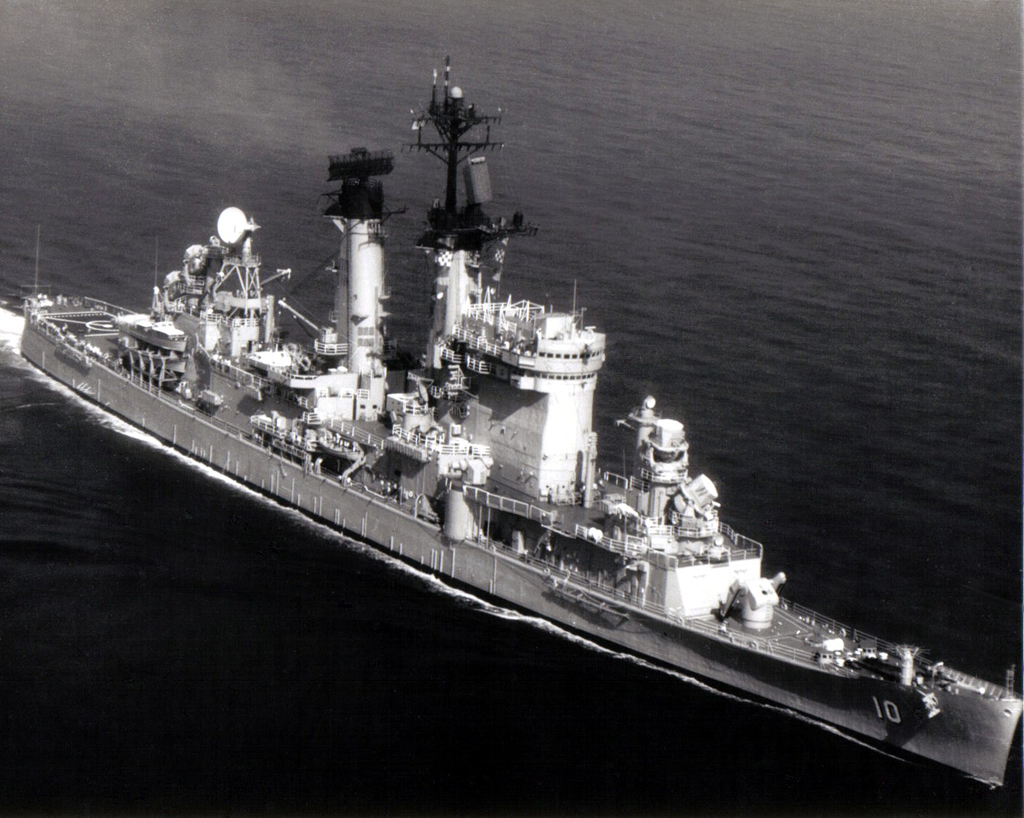
USS Albany CG-10 was a converted Oregon City class heavy cruiser. She was commissioned 3 November 1962 and decommissioned 29 August 1980. The Albany carried Talos and Tartar missile systems.
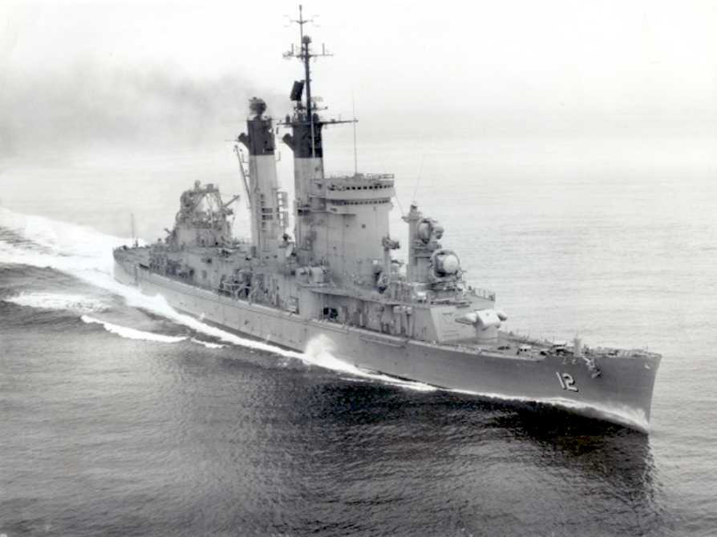
USS Columbus CG-12 was a converted Baltimore class heavy cruiser. She was commissioned 1 December 1962 and decommissioned 31 January 1975. Columbus carried Talos and Tartar missile systems.
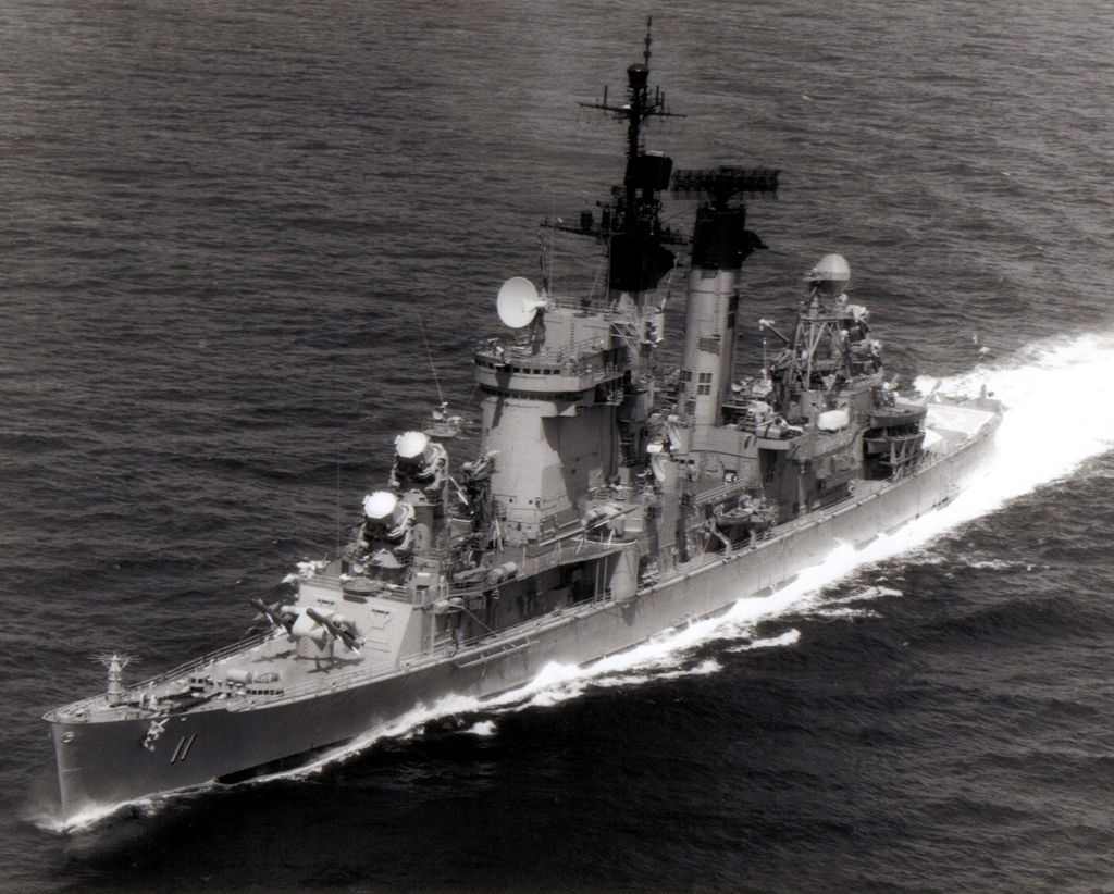
USS Chicago CG-11 was a converted Baltimore class heavy cruiser. She was commissioned 2 May 1964 and decommissioned 1 March 1980. Chicago carried Talos and Tartar missile systems. In July 1967 the Chicago shot down a drone at a range of 96 miles - this was the longest range Talos kill on record. On 9 May 1972 the Chicago shot down a MiG fighter at a range of 48 miles over North Vietnam with a Talos missile.16
Talos Land System
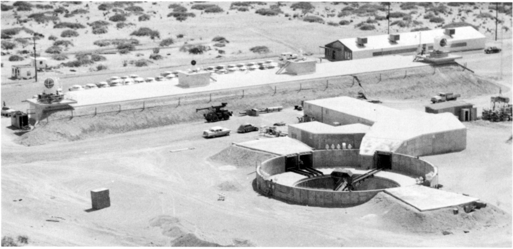
Talos was considered by the Army and Air Force for land defense of targets and the nuclear warhead version was considered as a possible ICBM interceptor.4 In 1955 a "roundhouse" installation was built by the Air Force at White Sands Missile Range, New Mexico, to test the missile as a point defense system for Strategic Air Command air bases. It functioned as a completely automatic system from target designation to intercept and was the most advanced antiaircraft system in existence.
Meanwhile, the Army and Air Force were squabbling over which service should be operating ground based air defense systems. In 1956 the Senate Armed Services Committee ended the bickering by awarding the Army responsibility for land based missiles with a range up to 200 miles. The completed and ready to run Talos Land System was turned over to the Army for evaluation. The Army was developing its own Nike Hercules anti aircraft missile system and had little interest in Talos, even though Talos was operational and Hercules was not. The Army decided to cancel the Talos Land System and disassembled the facility at White Sands.11
Talos Requiem
From the commissioning of the USS Galveston in 1958 to the decommissioning of the USS Oklahoma City in 1979 Talos missiles defended the fleet. Eventually all of the Talos ships were suffering from old age and were decommissioned, and no new Talos ships were built.
The Talos system was retired because of several shortcomings. The missile required guidance from the ship for the full duration of the flight, limiting the number of missiles that could be controlled by a ship. This made it susceptible to saturation attacks by large numbers of aircraft or missiles. Talos lacked adequate long range target discrimination (friend or foe) that made it unusable in proximity to friendly aircraft. This forced Task Group commanders to choose between engaging attackers with missiles or with aircraft. The Talos system required a large amount of shipboard space, and was incompatible with post WWII ship designs. The missiles, launching and fire control systems required a lot of maintenance and were very expensive. Finally, the development of the Standard missile and the Aegis system made Talos obsolete.4
The following data are for the period 1955 to the last Talos flight in 1979. Overall missile success rate was greater than 80%, but the missile system (missiles, launching system and guidance system) success rate was only about 40%.14
| Configuration | Missile | Missiles Built |
Missile Firings | Missiles Remaining |
|
|---|---|---|---|---|---|
| WSMR | Fleet | ||||
| First Tactical Talos | RIM-8A | 229 | 137 | 40 | 52 |
| First Tactical Talos W | RIM-8B | 111 | 60 | 12 | 39 |
| Extended Range Talos | RIM-8C | 234 | 57 | 164 | 13 |
| Extended Range Talos W | RIM-8D | 101 | 32 | 56 | 13 |
| Unified Talos | RIM-8E-J | 1729 | 176 | 615 | 938 |
| Total | 2404 | 462 | 887 | 1055 | |
There are some problems with these numbers. If 2404 missiles were built and 1349 were fired, then 1055 missile remain. If 644 Vandals were fired after 1979 there are still at least 411 Talos missiles unaccounted for. Talos LAST expended 49 8D and 8F (modified 8D) missiles, but these should be in the pre-1979 figures. I know of a few Talos on display in museums, training centers, VFW posts, etc., and some have been scrapped, but where are the rest? Some Talos missiles were launched from the Pacific Missile Range and possibly other test facilities, and these are not shown in the table. Also, many Talos boosters were used to launch other types of experimental missiles like Typhon.

Some early models of Talos were used as surface targets for aerial gunnery practice after later models were introduced, and this will account for some of the "missing" missiles.2 These missiles have become a cleanup problem because three components were manufactured from a radioactive Magnesium-Thorium alloy that expanded/contracted very little with heating and cooling. The missiles contained a small amount of Thorium, but it is a low level radiation emitter, so missiles on public display do not pose a radiation hazard. But when they are scrapped the radioactive Thorium must be disposed of in accordance to low level radioactive waste handling rules.
After Talos
The first task of the Bumblebee Program was to develop an effective anti-aircraft missile to defend the fleet. Three missiles (Talos, Terrier and Tarter - the "three Ts") were developed and deployed. Terrier evolved into the Standard missile that is deployed today with Aegis missile ships. The Bumblebee Program produced a list of "firsts." Terrier was the first operational shipboard missile system in history. Talos was the first rocket launched supersonic ramjet propelled vehicle. It had the first interferometer homing guidance system. It was the first beamriding missile. Talos was the first missile to carry a tactical nuclear warhead, and the first with an expanding rod conventional warhead.
The second Bumblebee task for APL was the development of the Triton ramjet powered surface to surface cruise missile capable of traveling 2000 nmi at Mach 3 at an altitude of 70,000 feet. Several configurations were considered and the final version was powered by two ramjet engines and could be launched from a Polaris missile launch tube. The engines were tested but the missile was not developed. Ramjets must fly within the atmosphere and had to be guided to their targets. These requirements presented problems in the 1950s. The autonomous guidance systems were large and heavy and unreliable, and special materials were needed to handle the heat generated by atmospheric friction. Triton was canceled in 1958 in favor of the Polaris submarine launched ICBM.7
In 1957 the Navy decided to continue development of a "super Talos" ramjet, called Typhon. This was APL's third Bumblebee ramjet. A new ramjet powered missile was designed to engage long range targets and a shorter range solid rocket powered missile would engage close in targets.
The Typhon LR long range missile used an improved subsonic combustion Mach 4 ramjet that was developed by APL. It had a conical inlet can combustor ramjet that was more efficient than Talos. The missile was much smaller than Talos but could cruise at Mach 4.1 at 80,000 to 100,000 feet with a range of 200 nmi. It carried a 250 lb warhead. It was 16.75 inches diameter and weighed 1800 pounds. It was flight tested nine times from 1961-63 with no propulsion failures. The LR missile had a unique guidance system based upon ground (ship) processing of target information sent by the missile. The Typhon MR medium range missile was to be a modified Tartar missile.6
The Typhon system developed a phased array radar utilizing new solid state technology and digital computers that could respond quickly and deal with many targets. However, the shipboard radar acquisition and tracking systems were not reliable, the detection range performance was inadequate for tracking single or multiple targets, and the software for the new shipboard computers was immature.
Eventually the complexity of the phased array radar and associated computer systems exceeded allocated funding. The design concepts were beyond the ability of existing manufacturing capabilities. Even though an operating Typhon system had been installed in the USS Norton Sound AVM-1 and the Typhon LR missile had proven reliable during in-flight testing, the missile could outperform its radar and guidance systems, so it was canceled in late 1965. The funds were transferred to improving existing Talos, Terrier and Tartar systems.6 The prototype Typhon fire control system later evolved into the Aegis weapons system.7
References
1. Bumblebee Initial Report, The Johns Hopkins University Applied Physics Laboratory, February, 1945.
2. Consultative Letter, IOH-SD-BR-CL-2004-0078, Radiological Assessment Survey of the Syracuse ANG Andirondack Range 48, Spraugeville NY, Department of the Air Force, Air Force Institute For Operational Health (AFMC), Brooks City-Base, Texas, 30 July 2004.
3. Dictionary of American Naval Fighting Ships, Department of the Navy, Naval History and Heritage Command, https://www.history.navy.mil/research/histories/ship-histories/danfs/s/savannah-iv.html
4. Evolution of the Talos Missile, William Garten, Jr. and Frank A. Dean, Johns Hopkins APL Technical Digest, Vol 3 No 2, 1982, p 117.
5. The First Forty Years, Chapter 1, The VT Fuze - Secret Weapon of World War II, Johns Hopkins University Applied Physics Laboratory, Schneidereith & Sons, Baltimore Md, 1983.
6. The First Forty Years, Chapter 3, The Missile Age, Johns Hopkins University Applied Physics Laboratory, Schneidereith & Sons, Baltimore Md, 1983, page 19.
7. History of Ramjet and Scramjet Propulsion Development for U.S. Navy Missiles, Paul J. Waltrup, Michael E. White, Frederick Zarlingo and Edward S. Gravlin, Johns Hopkins APL Technical Digest, Vol 18 No 2, 1997, p 234.
8. History of U. S. Navy Ramjet, Scramjet, and Mixed-Cycle Propulsion Development, P. J. Waltrup, M. E. White, F. Zarlingo, and E. S. Gravlin, AIAA Meeting Papers on Disk, July 1995, A9637264 AIAA Paper 96-3152 American Institute of Aeronautics and Astronautics, 1966.
9. RIM-8, Directory of U.S. Military Rockets and Missiles, http://www.designation-systems.net/dusrm/m-8.html
10. Talos Guidance System, Joseph Gulick, W. Coleman Hyatt and Oscar M. Martin, Jr., Johns Hopkins APL Technical Digest, Vol 3 No 2, 1982, p142.
11. The Talos Land System, Johns Hopkins APL Technical Digest, Vol 3 No 2, 1982, p 161.
12. Talos Low Altitude Supersonic Target (LAST) Missile, D. E. Madsen, Naval Ordnance Bulletin, June 1973, page 41.
13. The Talos Propulsion System, William B. Shippen, Walter G. Berl, William Garten Jr., and Everett J. Hardgrave, Jr., Johns Hopkins APL Technical Digest Vol. 3, No. 2, 1982, page 127.
14. The Unified Talos, Frank A. Dean, Johns Hopkins APL Technical Digest Vol. 3, No. 2, 1982, page 123.
15. Vandal-EER (MQM-8) Aerial Target, Space Vector Corporation.
16. When Computers Went to Sea, David L. Boslaugh, IEEE Computer Society Press, 2003, page 354.
17. An Overview of Some Monoplanar Missile Programs, M. Leroy Spearman, NASA Technical Memorandum 86330, National Aeronautics and Space Administration, Langley research Center, December 1984, page 7.
18. U. S. Navy Bureau of Ordnance In World War II, Buford Rowland and William B. Boyd, Bureau of Ordnance, Department of the Navy, U. S. Government Printing Office, 1953, 539 pages.