
RIM-8 Talos was a long-range high-altitude cruise missile designed to give the fleet stand-off protection against enemy aircraft and the ability to attack distant surface targets. It could attack aircraft, missiles, ships, radar installations and other shore facilities with either conventional or nuclear warheads. Talos had an effective range of about 100 miles and could engage airborne targets from 50 feet to 70,000 feet altitude.
Talos was the first surface-to-air and surface-to-surface guided missile developed by the U.S. Navy. It was a product of the Bumblebee program that started during World War II, along with the other "Ts", RIM-2 Terrier and RIM-24 Tartar. Damage inflicted by Japanese Kamikaze aircraft and German guided air to surface missiles and glide bombs during World War II brought light to the need for more effective fleet air defense. The three "Ts" were the first fleet missile defenses against the rapidly developing aircraft and missile threats.
Talos was the first operational beam riding missile and the first with semi-active homing. It was supposed to be the first antiaircraft missile deployed to the fleet, but because of the complexity of the Talos system and a series of performance improving design changes, the missile wasn't actually deployed until after the Terrier system was deployed. Originally intended for deployment in 1949, the missile didn't become operational until the commissioning of the USS Galveston CLG-3 in 1959.
The Talos missile relied upon guidance information from the firing ship. This limited the number of missiles a single ship could control at the same time. The guidance system transmitted a signal to direct the desired flight path. The missile followed this guidance signal to the target. A significant advantage of this beam riding control method was that the missile did not end up in a long, circuitous, fuel consuming tail chase as it approached the target. Instead the missile was guided to an altitude where it operated efficiently, and it was then flown to a predicted intercept point ahead of the target. This gave the missile a very long effective range. The ship illuminated the target with a signal from guidance radars and the missile homed in on the signal reflected from the target - this is called "semi-active homing." In the final phase of the intercept the missile dove on the target from above.
The Talos missile success rate was better than 80% but the overall system effectiveness was less than that. The Talos system occupied a huge amount of shipboard space and required a great deal of maintenance. A battery in the missiles had to be replaced monthly and each missile had to be tested every 60 days. In addition, the Talos system could track only six targets, and engage only two of these at a time. This made it vulnerable to saturation attacks by large numbers of aircraft. A relatively slow response time and long minimum intercept distance limited its effectiveness for countering low flying short range "pop up" targets. The last versions of Talos were introduced in the late 1960s. The anti-radiation RIM-8H missile carried additional electronics that allowed it to actively home on transmitting radars, and the RIM-8J used a high energy fuel that extended the range to 130 nautical miles. More than 2400 Talos missiles were built and about 1350 were fired in practice exercises and combat between 1958 and 1979. Unit cost has been reported as $386,000, or almost a billion (1960s) dollars for all.
The Talos launching system was was too large and expensive for most post World War II ship construction. Only one new ship was designed to carry it, the USS Long Beach CGN-9. Eventually Terrier was developed into the Navy's Standard missile, and Talos was retired from the fleet by 1979. The missiles continued to be used as land launched supersonic targets in the MQM-8 Vandal supersonic target program until 2005. For this use the missile was modified to allow it to fly in a surface-skimming cruise mode in addition to the normal high altitude mode. The Vandal targets contributed to the development of advanced Standard missiles. They were very challenging targets that were difficult to shoot down. Talos booster rockets were used to launch a variety of high altitude sounding rockets.
The Talos system was complex. Descriptions of various parts and operations can be found at these links:
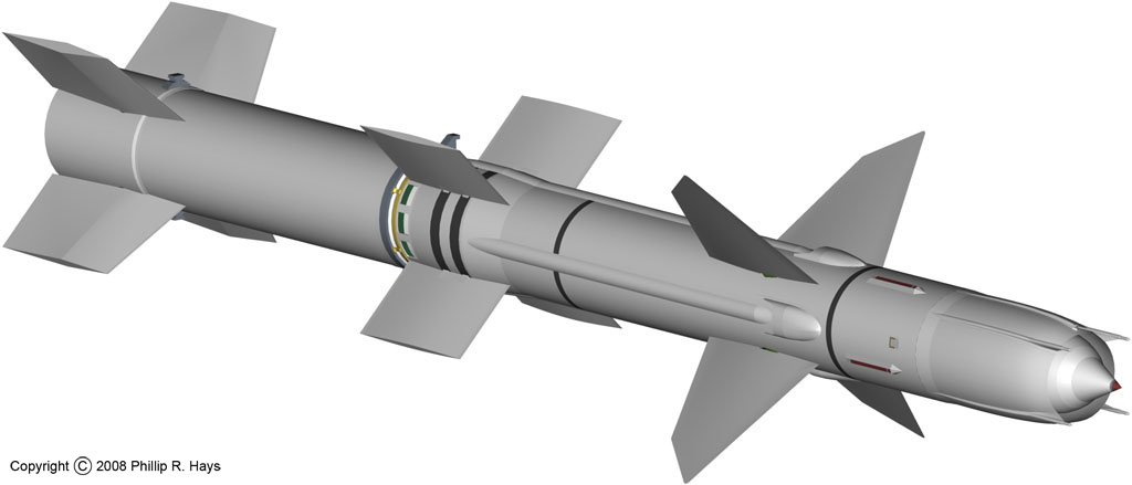
- Talos RIM-8 guided missile
- Talos Mk 7 Guided Missile Launching System
- Talos Mk 77 Guided Missile Fire Control System
- Talos missile firing operations
- Additional Talos information
- History of the Talos missile
References *
1. The Bumblebee Project, Evan D. Nau, 1998
2. Directory of U.S. Military Rockets and Missiles, RIM-8, Andreas Parsch, 2005
3. Evolution of the Talos Missile, William Garten, Jr. and Frank A. Dean, Johns Hopkins APL Technical Digest, Vol 3 No 2, 1982, p 117.
4. The First Forty Years, Chapter 3, The Missile Age, Johns Hopkins University Applied Physics Laboratory, Schneidereith & Sons, Baltimore Md, 1983, page 19.
5. Gunner's Mate Missile 3 & 2, Rate Training Manual NAVTRA 10199-B, Naval Training Command
6. Gunner's Mate Missile 1 & C, Rate Training Manual NAVTRA 10200-B, Naval Training Command
7. History of Ramjet and Scramjet Propulsion Development for U. S. Navy Missiles, Waltrup, P.J. et al, Johns Hopkins APL Technical Digest, Vol. 18, No. 2, 1997
8. Talos Missile Handling, Cruiser Installation, Technical Training Film Bulletin No. 45, Part II, Defense Atomic Support Agency
9. The Unified Talos, Frank A. Dean, Johns Hopkins APL Technical Digest Vol. 3, No. 2, 1982, page 123.
10. US Naval Weapons, Norman Friedman, Naval Institute Press, 1985.