
At the start of the Bumblebee Program in 1945 the aerodynamicists who were to design the new missile had little experience with supersonic flight. Some fundamental theories had been developed but most work had been on subsonic aircraft. Some test data were available for high speed projectiles, but there were no supersonic wind tunnels large enough to test missile designs.
The Ordnance Aerophysics Laboratory at Daingerfield, Texas, was developed to allow testing of models and engines at air speeds of Mach 1.25 to Mach 2.75 in a 19 x 27.5 inch test section. Early flight tests with high velocity rockets allowed data to be gathered on pressures, drag, wing loading and accelerations produced by moveable wings. Most tests were conducted at the Naval Ordnance Test Station at China Lake, near Inyokern California, and at White Sands Missile Range New Mexico.1
Initial flight control tests were conducted with a small subsonic rocket propelled Control Test Vehicle (CTV) in 1946. In 1947 a longer range two stage rocket powered Supersonic Test Vehicle (STV) was used to gain experience with supersonic flight control. The ramjet powered Experimental Prototype Missile (XPM) was developed in 1949. It was the first test vehicle to incorporate the ramjet propulsion, beamriding midcourse guidance and terminal homing features of the Talos missile. The XSAM-N-6 prototype Talos missile was flown from 1951 through 1954. The First Tactical Talos RIM-8A was introduced in 1955.
Boost Stabilization
The ramjet was boosted to operating speed by a large booster rocket. After the rocket was discarded the missile continued under its own power. This meant that the design must operate stably with two different aerodynamic configurations. The large wings were positioned near the missile's center of gravity where they were most effective for maneuvering the free flying missile. However, they were far ahead of the missile-booster combination center of gravity, therefore causing a destabilization of the combination during boost phase. This required the addition of very large stabilizing fins on the booster for the Experimental Prototype Missile. However, shipboard space was limited and large fins could not be used on a practical missile.
Active flight control during boost was the alternative, but flight conditions would be changing drastically and maneuvering during boost had never been tried before. The missile control system was designed to keep the unstable missile-booster combination on course during boost phase and then switch to normal missile control after booster separation.1
Wing Design
A cruciform (X shaped) wing pattern was determined by the need to maneuver in two planes in response to beamriding guidance commands. The wings provided lift in flight, steered the missile in pitch and yaw and stabilized it in roll.1 The four independently rotatable wings were located close to the missile's center of gravity, and operated as two sets of opposite pairs to move the missile in two orthogonal control planes. The wings provided most of the lift to keep the missile flying, so small changes in wing position would produce lateral or vertical accelerations to maneuver the missile. The wings were designed to produce accelerations over 14 g up to 40,000 feet altitude. Moving opposite wings in opposite directions caused the missile to roll about the long axis.2
Wing control at the center of gravity was chosen because it would cause the smallest change in the "angle of attack" while maneuvering. This was the difference between the direction the missile was pointing (along the long axis) and the direction it moved through the air. When the missile changed direction it rotated around the center of gravity, increasing the angle of attack. Large changes in the angle of attack would have significant effects upon airflow through the ramjet and that would cause the engine to lose power.1, 2
The Talos wings were rotated in response to guidance system commands. The rate of rotation affected how quickly the wings could produce force in a desired direction, and this determined how quickly the missile could respond to control system commands. The rate of wing rotation was 170° per second. The system adjusted control response for speeds ranging from low subsonic during boost phase to more than Mach 2 during the beamriding cruise phase. It compensated for altitude from sea level to 70,000 feet. The control system also corrected for the change of center of gravity as fuel was consumed.2
The servos that turned the wings were hydraulic, drawing their power from an air turbine pump. Pressurized air from inside the ramjet diffuser passed through the turbine and was then vented outside to the low pressure atmosphere. A high pressure nitrogen reservoir provided power to drive the turbine for the few seconds of boosted flight when airflow through the missile was reduced. About 25 horsepower was required to drive the wing servos.2

Space for control mechanisms was limited by the large diffuser duct running down the center of the missile. The servo mechanisms had to be relatively small and therefore of limited power. Wing designs were studied to find one that allowed the smallest movements necessary to deflect the wings during maneuvering through the expected range of speeds. The wings were designed so the center of pressure on the wing surface changed little with changes of speed and with wing rotations. This allowed the axis of rotation to be chosen to minimize wing rotation, and this simplified the control system. The final wing design was known as the Bumblebee planform.1
Lift was provided by deflecting the wings the necessary amount to keep the missile in the guidance beam. This increased drag and loaded the wing structure and control mechanisms. A wing design was needed that minimized drag but still gave sufficient maneuverability with small servo motions. The final wing design had a biconvex cross section of two circular arcs that gave low drag. The wing was tapered in thickness and width to achieve weight reduction, being thickest at the base where it joined the missile. The tip was angled appropriate for supersonic flight to reduce the loss of lift. The resulting wing operated well over a wide Mach number range. It has been used on many other U.S. and foreign missiles.1
Tail Fins
The initial design called for differential deflection of the wings to achieve roll stabilization, calling for a roll control system as well as pitch and yaw control. The three angular motions were controlled by deflecting the four wing panels in opposite pairs to achieve the desired motion. When this was tried in the Supersonic Test Vehicles the roll produced was opposite of what had been expected. Airflow interactions with the small missile tail fins on the early missiles was causing the unexpected behavior. The first solution was to install roll control surfaces on the tail fins but this complicated the design and added weight. After the complex interactions were better understood the tail fins were redesigned to eliminate the problem and control was again accomplished with the wings.1
Exhaust Vents
During boost phase a resonance started in the air column inside the prototype missiles, causing violent vibrations that damaged gyros causing missile failure and preventing good separation of the missile and booster. The solution was to add exhaust vents at the tail of the missile to relieve pressure during boost. Fortunately this did not cause any undesirable aerodynamic behavior, primarily because the vents were near the center of gravity of the missile-booster combination where the exhausted air did not interfere with booster fin effectiveness.1
Airframe Flexing
The Talos airframe bent while maneuvering. When the main loading on an airframe is at a single point, as it is with the Talos wings, the airframe may flex to produce a "banana-shaped" body. This changed the aerodynamic characteristics and these variations had to be accounted for in the control program. Talos had a fairly rigid aft section where the fuel tank and engine were located, but a less rigid hollow forward diffuser section. Flexibility of the structure required significantly larger wing motions at lower altitudes to achieve the desired maneuverability. At high altitudes where the air was thinner air loading was less of a problem and the structure flexed much less.1
The Talos airframe also had vibrational modes that could effect control system components, especially sensors that measured control system performance. These instruments were positioned where they would be effected least, but even then the signals had to be filtered to reduce vibrational "noise." Maximum vibration was at the center of gravity so the wings had to be designed so they wouldn't resonate or flutter at common vibrational frequencies. All of the information about vibrations had to be determined by experimentation in wind tunnels and test vehicle flights.2
Flight Characteristics
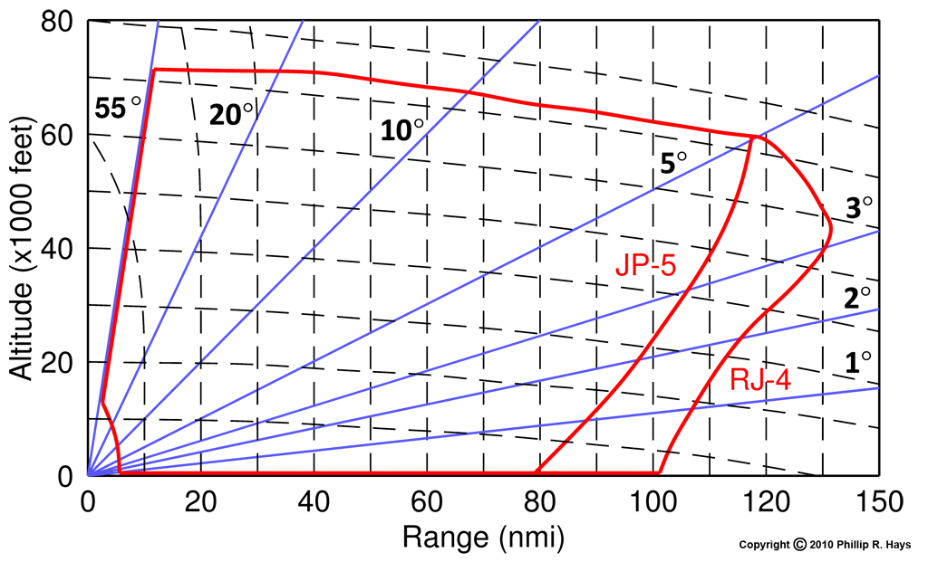
The graph shows the flight envelope for the Unified Talos RIM-8G missile burning JP-5 fuel and the RIM-8J with RJ-4 (dimer) fuel.3 The maximum launch angle was 55° and the maximum altitude was above 70,000 feet. The minimum intercept range was the distance for the booster to burn plus six seconds of flight time to acquire and home on the target, or about 8 to 10 miles.
The maximum range at 70,000 feet was 118 nmi with JP-5 aviation gasoline and 123 nmi with RJ-4 dimer jet fuel. The dimer fuel improved range considerably at lower altitudes, with a maximum range of 130+ nmi at 56,000 feet. Range decreased at lower altitudes, partly because of increased air friction in the denser atmosphere. However, fuel flow was reduced at lower altitudes to maintain optimum engine performance and this also reduced speed somewhat.
References
1. Talos Aerodynamics, Lester L. Cronvitch, Johns Hopkins APL Technical Digest, Volume 3, Number 2, 1982, page138.
2. Talos Control System, Fletcher C. Paddison, Johns Hopkins APL Technical Digest, Volume 3, Number 2, 1982, page 154.
3. The Unified Talos, Frank A. Dean, Johns Hopkins APL Technical Digest Vol. 3, No. 2, 1982, page 123.