
At the start of the Bumblebee program one of the first tasks was to determine how the missile would be guided to the target. Some experiments with several different types of homing systems had already been done in the program that produced the SWOD-Mark 9 Bat anti-ship guided bomb, but these were all short range systems. Initial plans called for Talos to have a range of 20 miles, then it was extended to 50 miles, this was later extended to 100 miles, and then 130 miles. The methods for achieving long range guidance and homing were unknown in 1945.
An early missile guidance scheme was proposed in 1925. A rocket was to be equipped with photo cells on the tail fins. It would be launched into a searchlight beam and follow the beam to an aircraft illuminated by the searchlight. The photocells would provide signals to a guidance system to keep the rocket in the beam. During World War II the British experimented with the Brakemine radar beam riding anti-aircraft missile. Neither of these missiles was produced, but the beam riding scheme was the basis for early Bumblebee missile guidance systems.5
The Bumblebee guidance concepts were based upon pulsed radar technology that was in use at the end of World War II. It was thought initially that the missile could follow the target tracking radar signal to the target. However, the accuracy of a beam riding system depends upon the width of the guiding beam, and the beam width increases with distance from the radar. The effective area of defense is limited to ranges where the width of the beam equals the lethal radius of the warhead.8 Because of the spread of a radar beam the position of the missile could not be controlled accurately enough to ensure that it would pass close enough to destroy the target at a range beyond ten miles.10
For longer range intercepts some form of terminal homing was needed to guide the missile close enough to the target to destroy it. The missile could home on a radar signal reflected from the target. However, any practical antenna that could be mounted on the missile would be too small to detect weak signals from the target at long ranges. Therefore the missile could not home on the target all the way from launch.8
The limited space available in the missile and the small antenna size also meant that the missile could not carry a transmitter powerful enough to illuminate the target at long ranges (active homing). The target would have to be illuminated by the ship's radar and the missile would home on the signal reflected from the target (semi-active homing).
A guidance scheme was devised consisting of midcourse beam riding to deliver the missile to the vicinity of the target followed by a semi-active homing phase to allow the missile to find and destroy the target. This system worked equally well at all target ranges and gave miss distances short enough to ensure a high probability of destroying the target.10 The combination of beam rider and terminal homing allowed a much larger area to be defended than either system alone.8
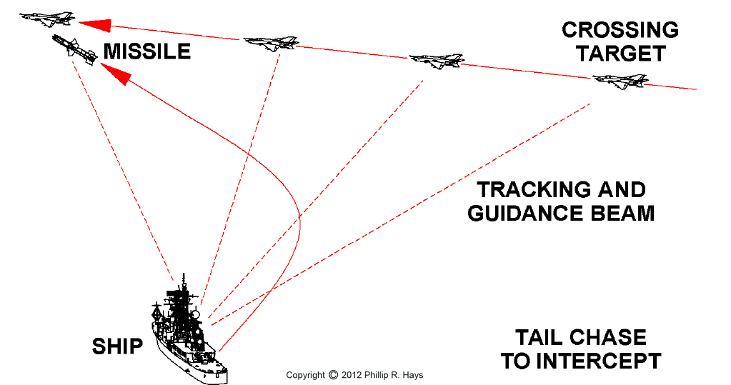
The simplest homing method is to let the target tracking radar beam function as the guidance beam to steer the missile to the target. This works if the target is flying directly at the ship with little change in bearing. However, if it is a "crossing target" that is flying perpendicular to the line of sight to the ship with a high bearing rate, the intercept problem is more difficult. As the target angle changes the tracking beam must be rotated to keep pointing at the target. This causes the missile to fly a long curved trajectory that always falls behind the target, resulting in a tail chase. In this situation the missile can only close the target at a rate that is the difference between the speeds of the missile and target. If the target is as fast or faster than the missile there can be no intercept. Even if the missile is faster it may run out of fuel before it catches the target. More advanced versions of the tracking beam guidance scheme used "Proportional Navigation" to aim the missile ahead of the target, but the missile still had to remain in the tracking beam, causing it to fly an inefficient curving path to the target.
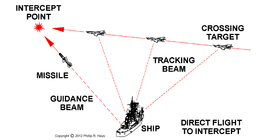
To achieve long range intercepts the missile must use fuel efficiently and fly the shortest possible path to the intercept. The ramjet engine operated most efficiently at high altitudes. The most effective use of the missile was to launch it into a high altitude cruise and guide it to an intercept point ahead of the target. This required separate radar beams for target tracking and missile guidance. This scheme had the virtue that the two radars could be optimized to their respective tasks. A fire control computer used target position information from the tracking radar and missile position information from the guidance radar to calculate an intercept point, and then steered the guidance beam to deliver the missile to the target.
The initial Talos guidance system was based upon World War II designs. It was relatively simple by today's standards, and worked only as a result of the development of many new electronic, hydraulic, electromechanical and sensing systems as part of the Bumblebee Program. These new systems were used in many subsequent missiles and airplanes.9
Early Guidance and Homing Flight Tests
At the start of the Bumblebee Program a test vehicle was needed to perform flight tests of beam riding control. Since a practical ramjet engine was not yet available a small subsonic rocket propelled Control Test Vehicle (CTV) was developed and flown in 1946.2 Flight tests were conducted at the China Lake test center near Inyokern, California.
In 1947 a longer range two stage rocket powered Supersonic Test Vehicle (STV, also called Steering Test Vehicle3) was flown to continue beamrider tests and to gain experience with supersonic flight control. The most advanced of these test vehicles, STV-3, incorporated most of the original Bumblebee Program design goals, with the exception of the ramjet engine. Because the ramjet powered Talos was still years away, in 1950 the Navy decided to develop the STV-3 into a new missile, designated "Terrier." In 1955 the STV-5 was developed to test tail control steering, and it became the Tartar missile in 1959. Tail control principals learned with STV-5 were incorporated into the Advanced Terrier missile in 1958.3
The ramjet powered Experimental Prototype Missile (XPM) was developed in 1949. It was the first test vehicle to incorporate the ramjet propulsion, beam riding midcourse guidance and terminal homing features of the Talos missile.2 In March 1951 an XPM achieved the first target kill by colliding with a target drone.3
The XSAM-N-6 prototype Talos missile was flown from 1951 through 1954. XSAM-N-6W prototype nuclear armed Talos followed in 1953.2 In October 1952 the prototype Talos interferometer homing system succeeded in homing on a target and destroying it.3 The First Tactical Talos RIM-8A was introduced in 1955.
Flights were divided into boost, midcourse and homing phases. The missile flew four basic trajectories, depending upon the range to the target and the electronic countermeasures environment. For short range targets it flew directly to the target after booster separation. For medium range targets (up 100,000 yard range) it flew an up and over arc. However, in a jamming environment it flew low to be under the horizon from distant jammers and then climbed directly at the target. For long range targets (greater than 90,000 yards) it climbed to high altitude and then cruised at a constant altitude to the vicinity of the target. There it dove to home on the target.11
Boost Phase
The booster-missile combination was aerodynamically unstable, so during boost phase the control system actively stabilized the missile to keep it pointed in the same direction that it had at the time of launch. The missile was launched into a broad guidance beam from the AN/SPW-2 guidance transmitter and it was necessary to control the wings to provide lift to keep the missile in the beam.9
Just before launch an attitude free gyro was uncaged to produce orientation reference signals. If the missile veered off course the gyro produced an error signal that directed the control system to move the wings to reduce the error signal, bringing it back on course. Each pair of wings had an associated rate gyro to control wing motion to prevent over responding which would cause the missile to swing back and forth rapidly. Wings designed for supersonic flight were not very effective at low speed subsonic flight. As the missile picked up speed the effectiveness of the wings increased, so the "gain" of the control system was reduced by a factor of 2.6 at 1.75 seconds after launch.9
The missile had an inherent "up" direction that was determined by a roll free gyro that was uncaged at launch. This orientation was maintained during boost and midcourse flight. The flight dynamics were very different for the two flight phases and the missile responded to roll changes faster after booster separation. Again, a rate gyro prevented the missile from oscillating in response to roll commands, and the roll control system gain was adjusted for altitude.9
The missile could not be relied upon to maintain the initial course very accurately during boost. At the end of boost the missile might be dispersed anywhere within ± 5° of the guidance beam axis. This dispersion complicated the beam riding scheme. A capture beam as wide as missile dispersion was necessary. The minimum launching elevation angle had to be greater than the dispersion angle to prevent the missiles from crashing into the ocean.7 Furthermore, reflections from the water would produce multipath problems causing the missile to see multiple images of the guidance signal with different time delays. The beam angle must be high enough that little energy reflects from the ocean surface. The missile was launched at elevations from 25° to 55°.12
Sensitive receiving circuits may be exposed to signal levels of sufficient power to burn out the circuits when the missile is close to the launching ship during boost phase. A means was needed to shield inputs while the missile was in the vicinity of high powered shipboard transmitters, but allow full exposure after the missile was at a safe distance. An attenuator antenna cap made of low melting point metal was devised to protect the antennas while in the magazine and during launch. After launch air friction heated the surface of the cap until it reached the melting point of the metal. The molten metal was then blown away in the airstream. The cap had to melt away completely before the end of the boost phase.1
Boundary layer temperature rise is a non-linear function of airspeed. To ensure shielding the sensitive electronics until the missile was sufficiently far away from the ship a metal alloy was selected with a suitable melting point chosen from a velocity-distance curve for the missile and booster. For example, assume that the missile would be at a safe distance from the ship when it is moving 1100 feet per second. A 90°F temperature rise occurs at about 1100 feet per second. If you assume an antenna cap temperature of 70°F at launch the temperature would rise to 160°F when the missile was moving 1100 feet per second. Woods Metal alloy of 50% bismuth, 25% lead, 12.5% tin and 12.5% cadmium has a melting point of 158°F,1 so it would be a good choice for the antenna caps. Note: I do not know for certain that the Talos antenna caps were this Woods metal alloy.
Midcourse Phase
A speed sensing fuel control system controlled missile velocity after the booster separated and the ramjet ignited. By maintaining a constant velocity the control system did not have to correct system response time for varying velocities. The missile was aerodynamically stable so control was switched from boost attitude stabilization mode to the beam riding mode that controlled steering.9
The missile flew inside the radar guidance beam transmitted from the AN/SPW-2 on the launching ship. The beamrider receiver in the missile detected the missile's position in the guidance beam and produced control signals to turn the wings and steer the missile to the center of the beam. After the missile steered to the center of the wide boost mode beam the AN/SPW-2 beam width was narrowed for guiding the missile.10 A gravity bias was built into the system to maintain sufficient lift so the missile would not drop below the guidance beam.9
The control system response time was varied with altitude (air density) to prevent the missile from maneuvering too quickly and overshooting the guidance beam center and to prevent it from oscillating about its center of gravity (weathercock oscillation). The rate of response to wing motion varied with air density so control system sensitivity was programmed to change with altitude to compensate. Altitude was measured by instruments that sensed the static pressure of the atmosphere.9
The guidance beam itself was not aimed in the exact direction of the desired missile flight path. The center of the radar beam was aimed slightly away from the central flight path axis, and the beam was rotated around this axis producing a conical scan. The beam offset has been reported to be 0.85° from the rotation axis with a 3.5° beam width10 or an offset of 2° from the axis with a 4° wide beam.11
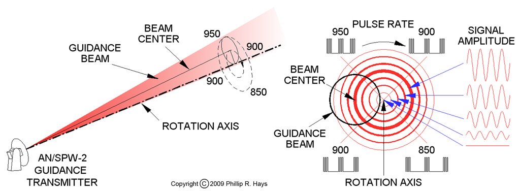
Each ship's guidance transmitter generated a pulsed signal in the 5 to 6 GHz portion of the C band that consisted of groups of three pulses at short intervals followed by a relatively long period with no pulses. The pulse group repetition rate was not constant, but was varied according to the position around the conical scan. The beam rotated to sweep around the conical scan 30 times per second, clockwise with respect to the direction from the ship to the missile. The pulse rate was changed from 850 pulse groups per second to 950 and back to 850 each time the beam circled around the rotation axis. The maximum pulse rate was 950 pulse groups per second at the upper left scan position and the minimum was 850 pulse groups per second at the lower right, as viewed from the ship to the missile.10 This produced a 30 Hz sinusoidal frequency modulated (FM) signal that was the timing reference for the beamrider guidance system.
Signal amplitude across the beam was not constant. The highest beam intensity was at the center of the beam, and the energy dropped off at the beam edges. In the conical sweep the highest signal strength was the cone where the beam center rotated. This is shown by the wider lines in the illustration. If the missile was flying along the rotation axis the amplitude of the guidance signal was constant. No matter where the beam was in its scan around the axis the distance from the beam center to the missile was the same, therefore the signal strength was the same. This told the missile that the distance to the desired flight path was zero - no maneuvering was necessary. If the missile strayed off the flight path the signal intensity would not be constant. When the beam swept around to the side of the rotation axis where the missile was flying the signal strength increased, and when it rotated to the opposite side of the axis the signal strength decreased. The missile detected a signal that alternately increased and decreased in amplitude at the 30 Hz beam rotation frequency. The timing of this amplitude modulated (AM) signal relative to the FM reference signal was dependent upon the position of the missile in the guidance beam.10
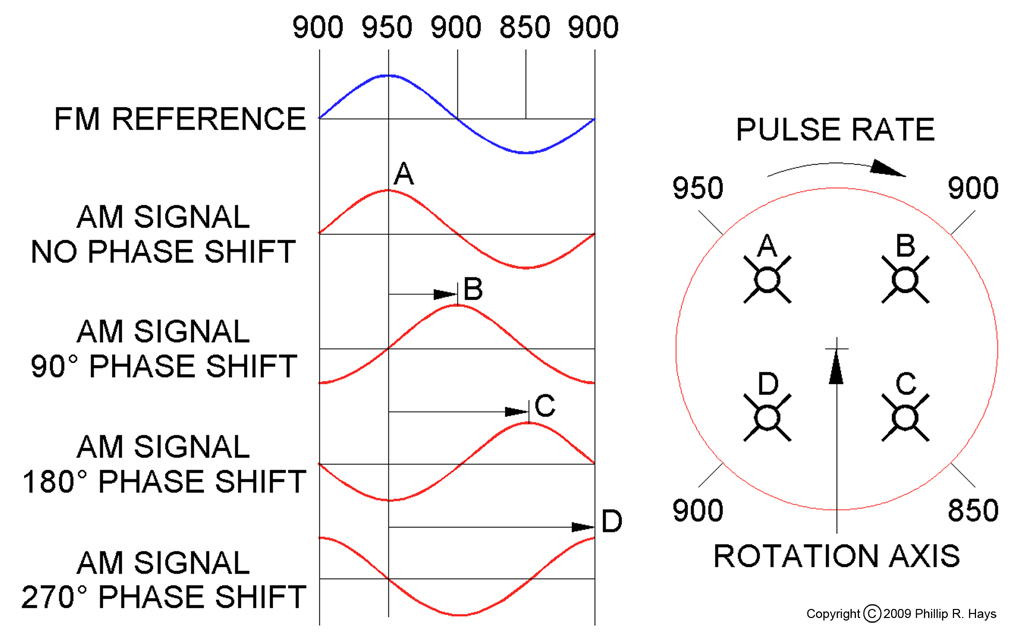
An antenna on the tail end of the missile detected the guidance signal for the beamrider receiver. The output pulses from the receiver passed to a 30 Hz amplitude modulation (AM) detector and a 30 Hz frequency modulation (FM) detector. The missile compared the timing of the peaks of the amplitude signal (missile position) with that of the frequency signal (beam position) to determine the phase relationship. For example, if the AM peak occurred at the same time as the FM peak the missile was high to the left of the beam axis. If the AM peak occurred at the same time as the FM minimum the missile was low to the right. The phase relationship between the two signals determined which way the missile should steer to get back to the beam axis. The output of the phase detector was fed to circuits that derived the correct combination of wing motions to steer the missile to the beam axis.
The direction to the beam axis was relative to the guidance beam, but the missile calculated wing controls relative to the missile. This made the guidance control very sensitive to missile motion. The missile was roll stabilized during beam riding by a roll free gyro so it could compensate for missile motion.10
The interval between the three pulses in the pulse group was different for each guidance transmitter, providing an identification code for the transmitter. While the missile was on the launcher it was told what pulse group code to look for so it would follow only that guidance beam. This prevented different guidance systems from interfering with each other. If guidance beams crossed each missile would ignore the beam with the wrong pulse code and stay in its own beam.10
Pulse groups were decoded to detect the appropriate signal, and the decoder generated one output pulse for each valid code group. This receiver output pulse was fed to the AM and FM detectors and to a beacon transmitter that drove an antenna on the rear of the missile. The 5 to 6 GHz beacon signal from the missile was detected by the AN/SPW-2 receiver on the ship and used to determine bearing and range to the missile for use in the fire control solution computer.10
The Mk 111 fire control computer on the launching ship used target bearing and range signals from the tracking radars and missile bearing and range information from the beacon receiver to compute the signals to control the guidance transmitter to guide the missile to the target. When the distance between the missile and target became small the computer sent a command through the guidance beam to the missile to begin homing phase.10
The ship might be rolling and pitching in heavy seas, causing the beam from the guidance transmitter to rotate. The fire control computer had a gyro "inertial element" to generate an error signal to correct for ship motion. The guidance beam pulse rate was modulated to eliminate rotation errors caused by ship movement. The transmitter beam position was also compensated so it wouldn't sweep all over the sky as the ship pitched and rolled, causing the missile to fly like a drunken sailor.10
Homing Phase
When the missile was in the target vicinity the ship transmitted a signal in the guidance beam to activate the terminal phase of flight. The pressure (altitude) midflight control system was switched off and the terminal guidance system took control. Because the missile would be maneuvering it was necessary to eliminate roll-yaw-pitch coupling. A roll rate gyro provided a signal to minimize the rate of roll.9
Target acquisition was achieved about ten seconds before intercept. This allowed sufficient time to adjust for missile heading errors and target maneuvers. The missile was steered on a collision course with the target by maintaining a constant bearing to the target while decreasing the range. The interferometer homing seeker produced rate signals proportional to changes in the line of sight bearing to the target. The control system generated wing movement commands to steer (accelerate) the missile to maintain an unchanging bearing to the target. The control system compared the requested acceleration to the actual acceleration and adjusted system gain to produce an optimum response to maneuvering commands. Talos was the first missile to use this sensitivity feedback system. This feedback system automatically corrected for changes of speed and altitude.9
During the homing phase the target was illuminated with a signal transmitted from the AN/SPG-49 target tracking radar on the launching ship. The missile homed on the signal reflected from the target. The missile flew a constant bearing decreasing range flight path to the target.10
To understand the constant bearing decreasing range principle imagine that you are driving down a road and you notice a car moving on another road that intersects the road you are traveling on. As you move toward the intersection the other car gets closer as it also approaches the intersection. If the other car is moving fast enough to arrive at the intersection first you will observe it moving across your field of vision so the angle between the car and the road you are on decreases. If it is going slowly so you will arrive at the intersection first, the angle between the car and your road will get larger. However, if the angle between the car and the road does not change it means you will arrive at the intersection at the same time the other car does. The angle (bearing) to the car is constant as you get closer to the intersection, but the distance (range) to the car decreases. In this situation if someone doesn't stop there will be a collision.10
Talos used a similar scheme to fly the missile to intercept the target. The missile did not aim at the target, it aimed at where the target would be at the time of the intercept, like the intersection of the two roads in the illustration. This produced the shortest, most direct flight to intercept, with the least maneuvering.
The design of the Talos homing target seeker was complicated by the large ramjet air intake. The seeker had to work without interfering with ramjet performance and it must acquire the target rapidly without needing information from the launching ship telling it the direction to the target. To intercept a target 100 miles from the launching ship the seeker needed good target resolution and high sensitivity.10
Gimballed parabolic and conical scan antennas were considered but they have the disadvantage that a moveable antenna on an airborne missile causes spin errors. Large antennas would block ramjet air intake and a radome around the antenna would distort incoming signals. The diameter of the antenna was restricted to the relatively small diameter of the missile with the inherent limitation in angular sensitivity.4
An interferometer homing system was chosen for several reasons. It would use small fixed antennas arranged around the ramjet air intake. These antennas were much less complicated and lighter weight than a gimbaled parabolic antenna. The interferometer would have a wide aperture to give accurate measurements of the rate of change of target bearing and it could acquire the target rapidly.10
The interferometer used two pairs of antennas, each pair positioned in one of the missile maneuvering planes corresponding to a pair of steering wings. Each pair of antennas drove a control system to produce movement in the associated pair of steering wings.
Unless the missile was flying directly at the target the homing signals reflected from the target would arrive at the two antennas in a pair at slightly different times. Consequently, the two signals would be out of phase. The homing receiver shifted the phase of one antenna signal and added it to the other antenna signal. The result was signal that reached maximum amplitude when the two signals were in phase. The amount of time (the phase shift) the signal had to be shifted to achieve maximum signal strength told the system the relative bearing to the target in the plane of the two antennas. The other antenna pair also gave information about the bearing in the second antenna plane.10
The homing system watched for changes in the target bearings. If the bearing changed in one plane the system generated wing control signals for the wings in that plane to turn the missile until the target bearing angle no longer changed. It did the same for the other antenna/wing pair. This kept the missile moving on a constant bearing, decreasing range course toward an intercept point ahead of the target.10
Because the system looked only for the rate of change of the bearing, amplitude variations in the received signals had no influence on the system. A gyro provided a signal proportional to missile motion to allow compensation for missile movement when determining changes in bearing to the target.10
The first Talos homing system had some problems inherent in the electronic components being used that caused homing errors. Slight variations in component characteristics caused differences in target bearing calculations that made some missiles work better than others. The system was redesigned to eliminate these problems. The new system was called Stable Platform Phase Follow-Up System (STAPFUS). It worked on the same principles described above, but the circuit modifications were designed to cancel the sources of error. After STAPFUS was incorporated into the homing system the majority of intercepts resulted in the missile crashing into the target (skin to skin contact).3, 7
Radars emit pulses of radio energy and look for reflections of the pulses from objects such as airplanes and missiles. The time delay from when the pulse is transmitted and the echo returns tells the distance to the target. The first Talos homing system used reflections from the target of the ship's AN/SPG-49 pulse mode tracking radar signal. This worked fine for high and medium altitude targets, but with low altitude targets the tracking radar signal scattered off of water, hills and anything else in the terrain, creating a clutter of signals that hid the target. A method of detecting a low flying target was needed.10
After the homing system was already in production for the RIM-8A First Tactical Talos missile a serious problem was discovered. Pulse seekers used range differences to discriminate targets and the pulse interferometer could not distinguish between two or more targets at the same range. Their reflections arrived at the interferometer at the same time and the signals were summed. The phase shift mechanism selected the strongest signal which was the sum of the two signals and produced a bearing that pointed in a direction between the targets. As the missile approached the target group the distances to individual targets changed so the timing of the signals arriving at the interferometer changed. The interferometer generated a series of different bearings causing the missile to gyrate from one bearing to the next and fly between the targets.4 If the targets were a few hundred feet apart the missile would miss them all.
Continuous Wave Homing System
Continuous wave (CW) seekers use velocity differences to distinguish targets.4 The Talos seeker was modified to use the Doppler effect to distinguish between multiple targets and ignore the background clutter. The AN/SPG-49 target tracking radars were modified to be able to produce both the high powered pulse mode tracking signal and a lower power continuous wave target illumination signal.
During the homing phase about 15 seconds before intercept the AN/SPG-49 tracking radar on the ship began transmitting a continuous wave illumination signal along with the pulsed tracking signal. Each target in a group of targets moved at a different speed relative to the missile, even if they were at the same distance. Because of the relative motions of the missile and targets each target reflected a signal that was Doppler shifted slightly in frequency. This allowed the missile to distinguish between the targets and home on the appropriate target.
Doppler shift is a change of frequency due to the motion between the source and the observer. We experience this when a car, train or airplane passes close by. We hear the sound of the engine, horn or whistle change frequency when the vehicle passes us. When it is approaching the frequency is higher, producing a higher pitch. When it passes and is moving away the sound has a lower pitch.
The CW homing system also solved the problem of detecting the target in a clutter of signals reflected from the background. Non-moving objects reflect the tracking radar signal back at the same frequency as the transmitted signal as shown on the left in the illustration. Moving objects reflect the signal back at a slightly higher frequency (if they are moving toward the radar) as shown on the right. In addition, the motion of the missile toward the target causes a second Doppler shift in the signal detected by the missile (not shown).10
The launching ship tracked the target and the missile. The Mk 111 fire control computer calculated the Doppler shift caused by the motion of the target moving toward the ship. Then it calculated the Doppler shift caused by the motion of the missile moving toward the target The correct homing frequency was encoded in the tracking radar signal. The tracking radar CW signal was frequency modulated with a frequency that was the sum of 400 kilohertz plus the calculated Doppler shift frequency for the specific target.10
An antenna on the rear of the missile detected the tracking radar signal and passed it to a receiver that determined the correct homing signal frequency. The missile's homing system had a programmable bandpass filter that allowed only a very narrow 100 Hertz range of frequencies to pass to the interferometer STAPFUS homing seeker. This filter was tuned to the frequency of the tracking radar while the missile was on the launcher so the initial bandpass frequency was very close to the final frequency. When the missile switched to homing mode the filter was set quickly to the new frequency sent from the ship. This allowed the missile to ignore non-moving background objects and other nearby moving objects to home on the specific moving target. The target was usually acquired in less than two seconds after the missile was switched to homing mode.10
Tests against surface targets showed that the CW seeker was effective against surface targets. There is no Doppler shift in the signals reflected from a ship and the ocean surface, but several other features of the seeker gave a suitable signal to noise ratio to allow the missile to home on surface targets.10
Multiple reflections were a problem for surface ship targets. The missile was moving at the same speed toward all parts of the ship , so multiple reflections with the correct Doppler shift were detected. As the missile to target range decreased the seeker began detecting reflections from several parts of the ship. The calculated target bearing shifted from point to point on the target causing the missile to maneuver violently in the last moments before intercept. This problem was solved by disabling the seeker shortly before intercept.
When a radar signal hits a target such as an aircraft or a ship, the reflections from multiple facets of the target can combine in strange ways. Sometimes this results in an apparent reflection point being outside the actual target, which can create a false intercept solution causing a missile to miss the target. This phenomenon is known as "glint". Glint is most evident in the plane of the target and transmitting radar. Because Talos dove on the target from above it was much less susceptible to homing errors caused by glint than missiles that flew at the same altitude as the target.
Home On Jamming
The CW homing receiver had several characteristics that made it less susceptible to countermeasures. The narrowband seeker rejected most jamming frequencies. The short 6 to 10 second homing period gave little time for countermeasure equipment to respond. The signal tracking method in the STAPFUS seeker was not sensitive to signal amplitude. The homing system could discriminate between multiple jammers and home on the strongest received signal. However there were some jamming techniques that would work against it. A new "monopulse" seeker was designed to precondition the interferometer to reject jamming interference before the signals were passed to the STAPFUS seeker, and a faster method of tuning to the search frequency was added. The resulting seeker was immune to virtually any type of jamming.10
After extensive laboratory testing the new seeker was flight tested against a variety of jamming targets. 25 of the initial 26 tests were successful with many direct hits. Test results showed that the new seeker had a higher probability of kill against a jamming target than against a non-jamming target. In essence a jammer broadcast a "here I am, come and get me" signal that Talos couldn't miss.10
Additional home on jamming improvements for the Talos seeker were devised but were never implemented because the phaseout of Talos was planned.10
Antiradiation Missile
The Talos Anti Radiation Missile (ARM) program was initiated in 1965 to produce a missile quickly for use against enemy radars in Vietnam. The missile's long range made it a good delivery platform and the modular design of the Unified Talos made it relatively easy to introduce new features. Just 35 days after the effort was started a successful flight test was conducted against a S-band radar target at White Sands Missile Range on October 26, 1965. The final ARM design was delivered to the fleet in 24 months.10
For ARM shots the ship did not track the target to generate midcourse guidance information for the missile. The target location and RF characteristics (frequency, pulse repetition rate, etc.) were determined ahead of time. Talos ships carried extensive electronics intelligence suites that were capable of detecting and identifying individual radars and determining the range and bearing to the transmitter. Ship position at launch was obtained by the Navy Navigation Satellite System (NAVSAT), a precursor of the Global Positioning System in use today. After launch the ship used ordinary beamrider midcourse guidance to direct the missile to the vicinity of the target radar. When near the target the missile was switched to terminal homing.10
The missile began the homing phase by diving toward a point four miles beyond the radar's expected location. The line of sight to the target changed in a downward direction and the seeker looked for signals with this characteristic. This allowed it to ignore other more distant radars. When the target was acquired the missile dove and homed on the transmitting antenna. The missile approached the target at either a 45° angle or dove nearly straight down on the target. Flight tests at White Sands produced many direct hits.10
The ARM seeker had the ability to home on single pulses (monopulse) with a low repetition rate that were characteristic of some radars. The seeker had high sensitivity to detect the weak side lobes emitted from the target radar (it did not have to attack directly into the radar beam). The ARM circuitry processed the signals from the interferometer antennas and then passed a signal to the STAPFUS seeker to steer the missile to the target.8
The Talos ARM missiles were used to destroy North Vietnamese air control and antiaircraft radars. The USS Oklahoma City was the first ship to destroy an enemy radar with the Talos ARM missile.
References
1. Antenna Cap, Billy D. Dobbins, Angus C. Tregida and George W. Luke, Jr., U.S. Patent No. 2,998,943, September 5, 1961.
2. Evolution of the Talos Missile, William Garten, Jr. and Frank A. Dean, Johns Hopkins APL Technical Digest, Volume 3, Number 2, 1982, page 117.
3. The First Forty Years, Chapter 3, The Missile Age, Johns Hopkins University Applied Physics Laboratory, Schneidereith & Sons, Baltimore Md, 1983, page 19.
4. Guidance System, Robert L. Kent, Rosario S. Badessa, Carl Barus, Joseph M. Dunn, Raymond Arthur Glaser and Leonard B. Johnson, U.S. Patent No. 3,477,666, November 11, 1969.
5. Gunner's Mate M 3 & 2, Missile Guidance and Control, Naval Training Support Command, NAVTRA 10199-B, 1972, page 81.
6. Inter-ferometer Homing System, Joseph F. Gulick, Thomas D. Jacot, Harlan H. Knapp and Hilary H. Nall, U.S. Patent No. 3,181,813, May 4, 1965.
7. Power Modulator for Transmitter Beam Scan, William L. Vann, U.S. Patent No. 3,290,599, December 6, 1966.
8. Scanning Interferometer-Beam Rider Guidance System, Carl W. Brown, Allen B. Reppert, Bill D. Dobbins, U.S. Patent No. 3,677,500, July 18, 1972.
9. Talos Control System, Fletcher C. Paddison, Johns Hopkins APL Technical Digest, Volume 3, Number 2, 1982, page 154.
10. Talos Guidance System, Joseph Gulick, W. Coleman Hyatt and Oscar M. Martin, Jr., Johns Hopkins APL Technical Digest, Volume 3, Number 2, 1982, page 142.
11. The Talos Ship System, Elmer D. Robinson, Johns Hopkins APL Technical Digest, Volume 3, Number 2, 1982, page 162.
12. The Unified Talos, Frank A. Dean, Johns Hopkins APL Technical Digest, Volume 3, Number 2, 1982, page 123.