
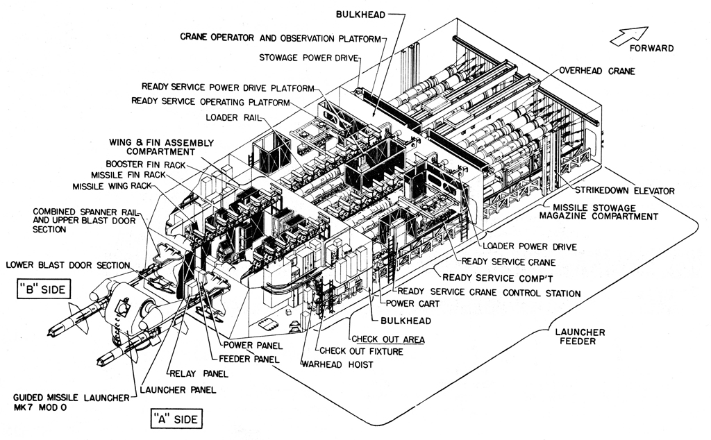
The Mk 7 Mod 0 Guided Missile Launching System (GMLS) consisted of a missile stowage magazine, ready service magazine, wing and fin assembly area, missile test cells, warhead magazine, launcher and numerous pieces of machinery to move the missiles, boosters and warheads throughout the missile house. The entire system, including missiles, added about 400,000 pounds on the main deck. The missile house was built of 1 1/2" armor plate, with armored vent covers and hatches to the outside. The magazines had large "blowout patches" in the house sides to vent pressure due to fire or explosions. Each area of the missile house was divided into separate port and starboard systems. Pneumatically operated armored doors opened outward to the main deck on the port and starboard sides in each area. These were primarily used for emergency access. Normal access to the missile house was through a hatch in the main deck in Area 1.

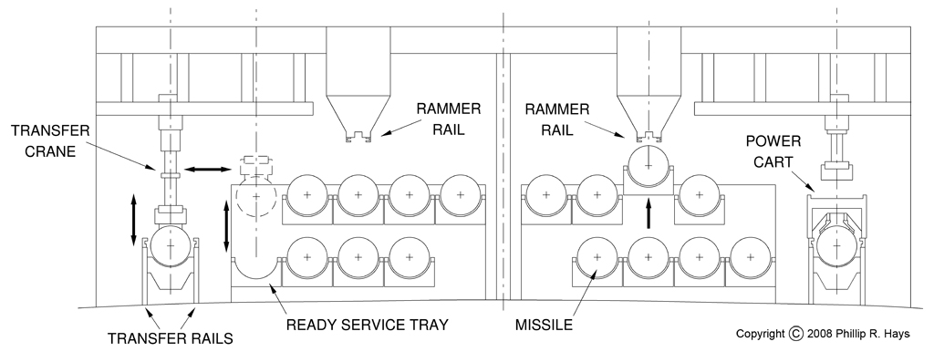
Port and starboard "rammer" rails ran from the Area 2 ready service magazine to the missile launcher to carry missiles from the magazine to the launcher. These passed through the Area 1 wing and fin area and through blast doors to the launcher. Two hydraulically operated fire doors opened momentarily to allow missiles to pass from Area 2 to Area 1 on the rammer rails.
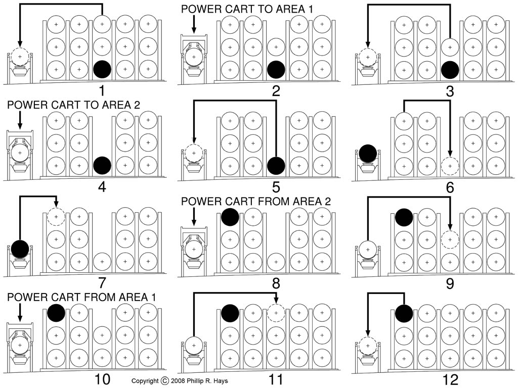
A pair of transfer rails ran down the outboard sides of the missile house connecting the stowage magazine, ready service magazine and test cells. A walkway ran the length of the missile house just inboard of the transfer rails. A pneumatically operated power cart running on these rails carried missiles and boosters between the areas. Because each missile had to be transferred to the test cell to change batteries every 30 days and for testing every 60 days, the transfer carts were kept busy.
Fire doors dropped through narrow gaps in the transfer rails to seal off the three areas. The doors would fall automatically in response to heat and pressure sensors in the magazines. The hydraulically powered doors could be opened and closed under operator control in a few seconds when the hydraulic pressure was high. They could also be opened manually with a small lever operated pump, but this took 10 to 15 minutes to open the door completely.
Missiles and boosters were moved into and out of the missile house through strikedown hatches in the O2 level deck over Area 3 on both sides of the ship. Strikedown elevators located between the transfer rails lowered and raised the missiles and boosters through the hatches. It was not possible to transfer missiles or boosters between the port and starboard sides inside the missile house. To do this it was necessary to raise the missile or booster on an elevator through the strikedown hatch in Area 3. Then a "grasshopper" transfer cart was used to roll the missile or booster across the top of the missile house to the strikedown hatch on the opposite side. There it was lowered back into Area 3 on the strikedown elevator. Since the ship did not normally carry the grasshopper carts, this maneuver could be done only during underway rearming with an ammunition ship or in port at a naval weapons depot.
Shipboard missile handling video
GMM 3&2 and GMM 1&C training manuals
Area 3 - Missile Stowage Magazine
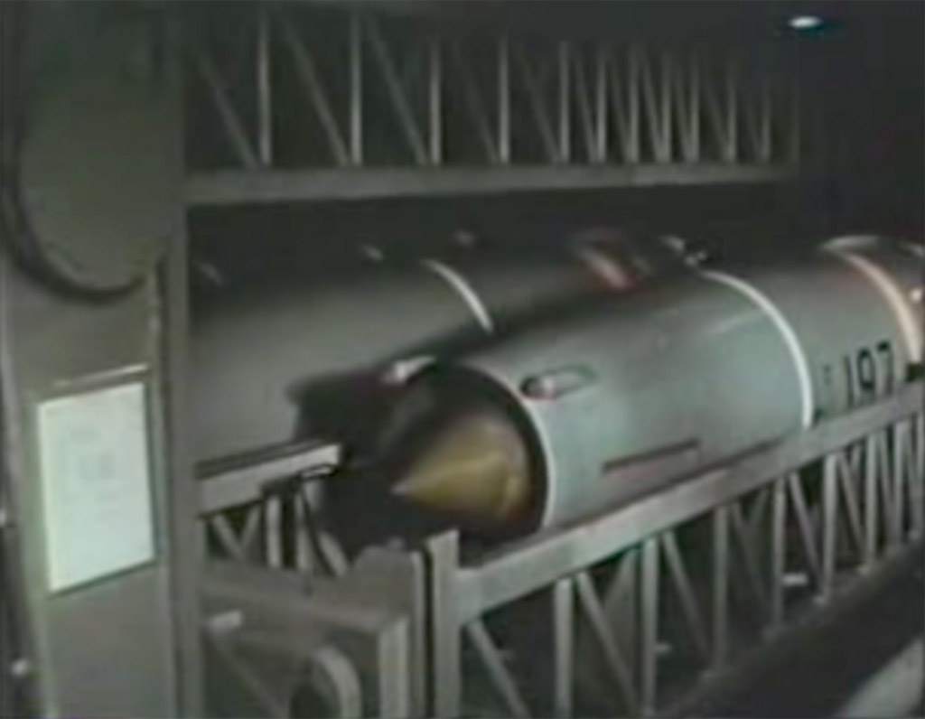
Missiles and boosters normally were stored unmated in the Missile Stowage Magazine, but mated missile-booster combinations could be stored there. Each missile was mated to a warhead. The magazine contained storage for 15 missiles and 15 boosters on each side, for a total of 30 of each. Port and starboard overhead bridge cranes could transfer missiles, boosters or mated sets between the storage stacks and support cradles located between the transfer rails.
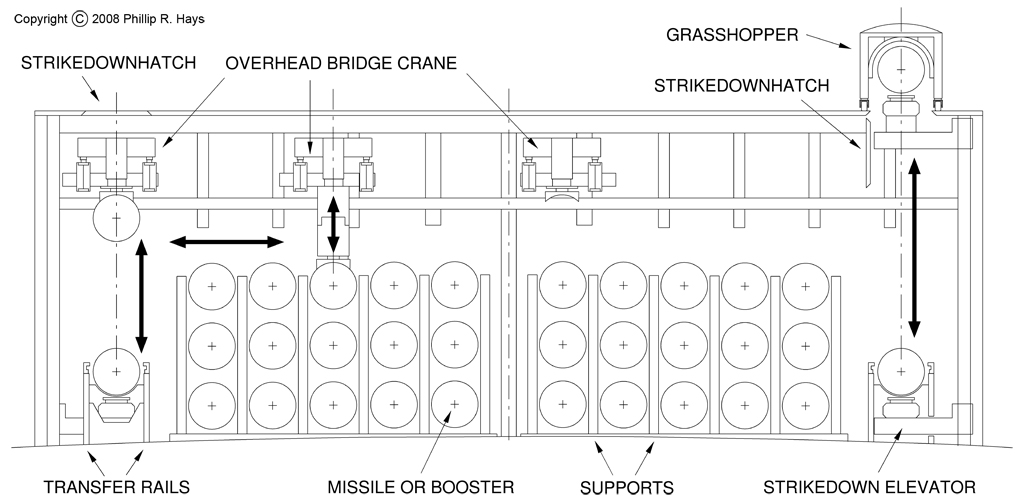
The "stacks" were made up of a forest of vertical support rails. One set of rails was spaced to hold missiles and another set, located behind the missiles, was spaced to hold boosters. Missiles and boosters were stowed three deep between the rails and were latched in place while in the stacks. Two storage bands with shoes that fit into slots in the rails were strapped around each missile and booster. The overhead crane latched onto to the storage bands to lift the missile or booster above the stacks. The crane could then travel inboard or outboard to move the missile or booster.
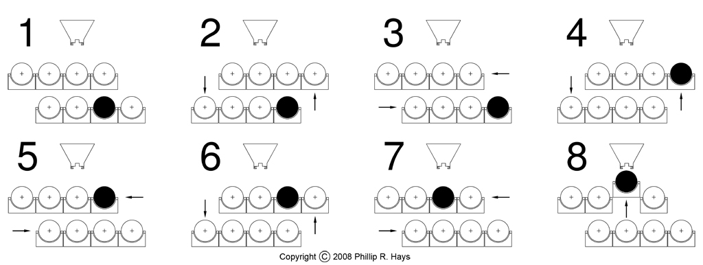
If the Stowage Magazine was full, getting a missile or booster out of a lower tier was a bit complicated:
1. The top missile was lifted from the stack and placed in the cradle between the transfer rails.
2. It was then carried to the Area 1 test cell with the power cart.
3. The next missile was moved to the transfer rails.
4. It was then carried to Area 2 with the power cart.
5. Then the subject missile was moved to the transfer rails.
6. Another missile on a top tier was then moved to the empty lower tier where the subject missile had been.
7. Next the subject missile would be moved to the vacant top tier position.
8 - 11. Now the missiles in Area 2 and Area 1 could be returned to the vacant positions in the stack.
12. Finally, the subject missile could be lifted out of the stack again and moved into Area 2 or Area 1.
Every missile had to be moved to the Area 1 test cell each month for maintenance, so the crew in Area 3 was busy most of the time. The crew put in long hours at sea to get the tests done so they would have lots of free time when in port.
The hydraulic systems in the Area 3 magazine were a unique problem in themselves. The hydraulic fluid was not flammable, so it did not present a fire hazard. This was a good thing because the machinery leaked like a sieve. The seals used in the system slowly decomposed in the hydraulic fluid, so after a while they began to break down and leaks appeared. It wasn't uncommon to find pools of hydraulic fluid on the deck between the supports for the stacks.
Area 2 - Ready Service Magazine
Missiles were stored mated to boosters and ready for launch in the Ready Service Magazine. Two independent port and starboard systems allowed selection of specific missiles for loading onto the launcher. The magazine held 16 missiles, eight in each ready service "ring." Control stations for operating the machinery in Area 2 were located on platforms on the O1 level above the ready service rings.
Missiles were stored in "trays" with the lower booster shoes latched into the tray.
1. Trays were arranged in two layers, with five positions on each layer but only four trays on the bottom and four above, leaving empty spaces on opposite sides above and below.
2. When the ring was "rotated" the top end tray that was positioned above an empty space below was lowered into the empty space. At the same time the lower tray on the opposite
side was raised into the empty space above.
3. Then the trays were moved sideways one position to fill the empty spaces, thereby creating empty spaces on the other side, just as in the starting condition.
4 - 7. The process was repeated until the desired missile was in the top center position beneath the rammer rail leading to the launcher.
8. The tray was raised until the upper shoes on the booster fit into slots in the rail. The missile was moved forward a short distance so it was supported
by the rail.
The lower booster shoes were released from the tray and the tray was lowered. Then a door to Area 1 opened and the missile was moved to the Wing and Fin Area.

An overhead transfer crane could move mated missiles between an assembly station between the transfer cart rails and the lower outboard tray. Missiles and boosters were assembled together or disassembled at this station. When a mated missile in a ready service ring was due for maintenance, that tray was rotated to the lower outboard position. The mated missile was lifted out of the tray and moved to the assembly station. There the clamp ring was released to separate the missile and booster. Then the missile was moved with the transfer cart to the test cell in Area 1. After the test was complete the process was reversed.
The assembled missile/booster was supported in the ready service tray by the shoes on the booster. The missile itself had no support other than the clamp ring attaching it to the booster. Soon after the Talos system was deployed into the fleet a problem was discovered. The missile/booster combination was essentially a long, slightly flexible rod that was fastened down at only one end (the booster). Consequently, it had a resonant frequency (about 13 Hz) at which it would oscillate. That was a vibration frequency generated by the propeller shafts at a certain speed. If the ship maintained that speed for very long the oscillation would build in the missiles and the clamp ring would open, allowing the missile to separate from the booster and drop into the tray. After this was discovered vibration dampers were installed in each tray.
The ready service rings were hydraulically operated. Fortunately, this equipment was produced by a different manufacturer than the Area 3 hydraulics. The fluid used in the ready service rings did not attack the seals so there were far fewer leaks in Area 2. Getting to the equipment to work on it was not always easy. Much of the plumbing ran beneath the ready service rings. To get to it the deck plates were removed from the walkway at one side and the workers would crawl into the approximately one foot high space under the trays.
Area 1 - Wing and Fin
Area 1 was divided into three sections. In the center under the port and starboard rammer rails was the Wing and Fin Area. Missiles were stowed in Area 3 and Area 2 without the wings and fins installed. Prior to firing mated missiles were moved into Area 1 on the launching rails. There crews manually installed the wings and fins on the missile and booster. The launcher control panel was located between the launching rails. Missile movement from Area 2 to the launcher was controlled there (movement could also be controlled automatically from Weapons Control). Wings and fins were stowed in racks on either side of the missile path through the area. The deck here was raised above the main deck level by about four feet. Additional wings and fins were stowed beneath the deck plates, along with spare parts and equipment and some GM Division personal belongings. The normal personnel entry to the missile house was from a guard room below on the 2nd deck (manned by an armed Marine guard), through a hatch in the main deck to Area 1.


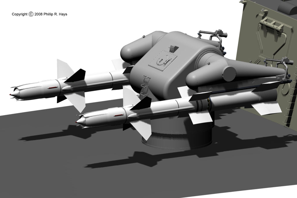
When a missile moved from the Ready Service Magazine it stopped at the wing and fin station where crews installed the 12 flight control surfaces. They also verified that the missile carried the correct Arming Plug. After the wings and fins were installed each crew member stepped behind a metal screen and depressed a foot switch. This signalled that every man was out of the movement path of the missile. The launching system moved the missile 12 feet per second and the wings and fins would cause severe injury if someone was in the way as the missile moved. Armored blast doors on the end of the missile house were opened and the missile was moved to the launcher. First the lower door was opened, swinging downward. Next the upper door swung upward. It carried an extension of the launching rail that filled the gap between the rail on the launcher and the rail in Area 1. The missile moved out of the missile house and onto the launcher and the blast doors were closed. Then Weapons Control and the guidance computer took over control of the launcher and missile.
The blast doors were hydraulically powered and opened very quickly. Anyone standing outside the missile house in front of the doors would be crushed when the massive lower door opened, so during non-firing tests a watch was stationed outside the missile house to verify the area was clear before the doors were opened. During firing exercises a watch was stationed at an observation window located in a small armored "house" on the fantail that extended above the main deck a foot or so. A narrow rotating window in the face of the missile house allowed an observer inside to see the area between the launcher and the house that was not visible to the fantail observer. The window was rotated behind an armored cover before the missile was launched.
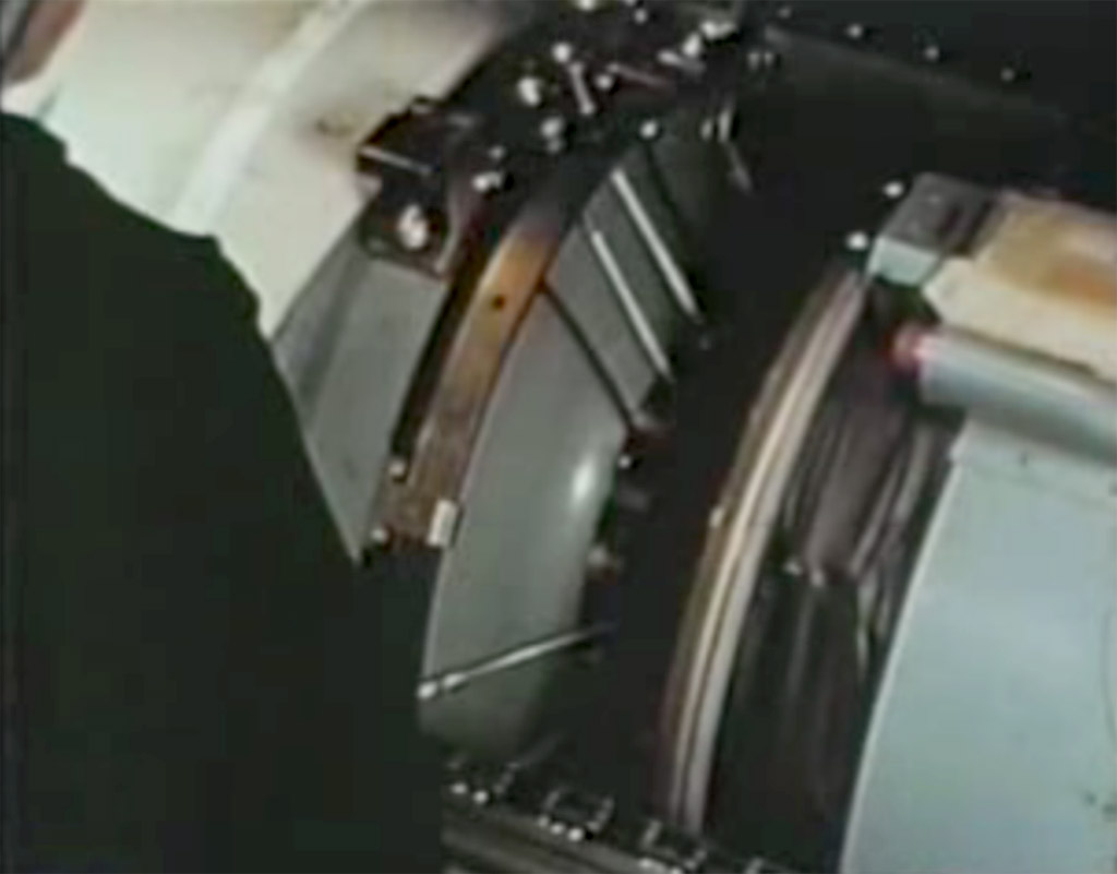
Inside the missile house at the main deck level on the port and starboard sides were missile test cells. The transfer rails from Area 2 ended at the test stations. Just beyond the end of the transfer rails on the main deck were hatches that opened into the Special Weapons Office below on the 2nd deck. Directly above these hatches were warhead strikedown hatches on the O2 level top of the missile house. Pneumatically operated warhead cranes ran on rails attached to the overhead beside the hatches to the O2 level. These hatches and the cranes were used to transfer missile warheads between missiles in the test cells and the Special Weapons Office. From there they could be moved to and from the warhead storage magazine on the 2nd platform deck.
The test cells contained hydraulic and electrical power supplies for the missile under test. During testing the missile electronic and hydraulic systems were powered up and checked to verify that everything worked correctly. Electrical connections to the missile ran up to the TATTE (TAlos Tactical Test Equipment) compartment directly above on the O1 level where the missile test equipment was located. The area also contained a work bench with a variety of electronics test and repair equipment where missile electronic modules were repaired. Access to the TATTE compartment was by a vertical ladder on the outboard side of the test cell.
After missile launch telemetry data from the in-flight missiles was received by a telemetry antenna. Receivers in the TATTE compartment recorded flight data from the missiles on long continuous rolls of ultraviolet light sensitive paper. Extremely bright ultraviolet lights exposed trace lines on the paper. During a flight many tens of feet of this eight inch wide ribbon shot out of the recorder at several feet per second. It poured through the opening in the TATTE cell deck and piled up in the test cell below. After the flight this paper was "developed" by exposing it to bright visible light, leaving dark lines showing the recorded data. This allowed post flight analysis of missile operation and confirmation that the missile detected the target and detonated.
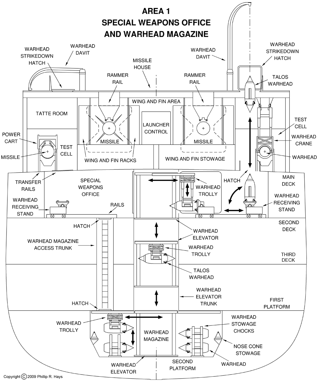
Warhead Magazine
Unmated warheads were stored in the Missile Warhead Magazine located between the shaft alleys on the 2nd Platform Deck about 35 feet below Area 1. Both conventional and nuclear warheads could be stored there. Warheads were stowed without the nose cone attached in hold-down "chocks" on each side of the magazine. The nose cones were stowed in brackets on the bulkheads.
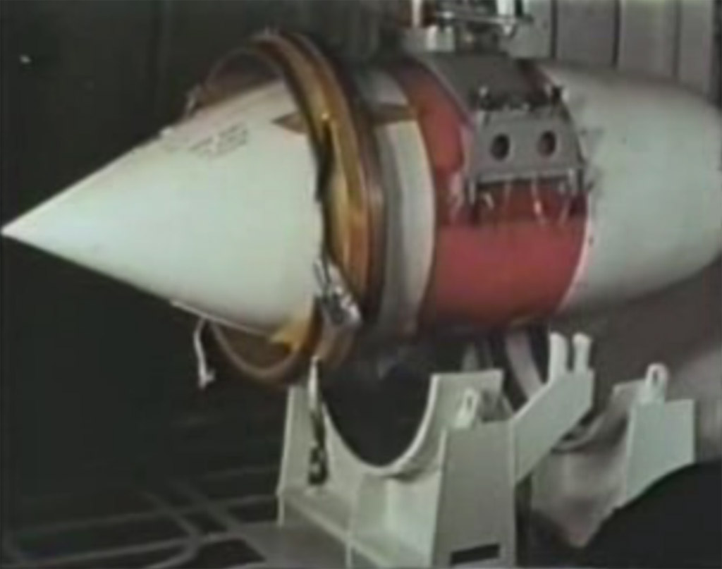
The chocks consisted of six pieces designed to hold two warheads. Two U-shaped base pieces were fastened to the deck to form a warhead "cradle." After a warhead was placed in the base pieces, center spacers were placed over the warhead near each end and bolted to the bases. The center pieces were shaped like two "Us" attached at their bases, one to fit over the lower warhead and the other to hold the upper warhead. When in place over the lower warhead the center pieces formed a second warhead cradle. After another warhead was positioned in the center pieces two top brackets were bolted in place. The openings in the cradles were rubber lined and fit tightly around the warheads. When fastened in place in the chocks a warhead could not move.
Carrying brackets were attached to the warhead sides when it was to be moved. The upper parts of the chocks were removed and a pneumatic powered Warhead Trolley riding on overhead rails was positioned over the warhead. A crane on the trolley was lowered and attached to the carrying brackets. Then the warhead was lifted from the chock and carried by the trolley.
The Warhead Elevator Trunk descended from the Special Weapons Office on the 2nd deck down three levels to the magazine. The elevator trunk was sealed by watertight doors at the top. The trolley carrying the warhead was driven onto rails running the length of the magazine, and from there to mating rails on the elevator and locked in place. Then the elevator was raised to the 2nd deck level.
In the Special Weapons Office there were two pneumatic powered transfer carts called Warhead Receiving Stands. These rode on rails on the deck to port and starboard of the elevator trunk. Each Receiving Stand had a warhead mating bracket that could be rotated from horizontal to vertical. This bracket was rotated horizontal and the Receiving Stand was driven up to the elevator trunk. Then the trolley on the elevator was positioned so the four missile attachment struts on the warhead mated with four attachment points on the warhead mating bracket. After the warhead was fastened to the Receiving Stand it was released from the Warhead Trolley on the elevator.
Then the Receiving Stand was driven away from the elevator and the mating bracket was rotated to the vertical position so the warhead nose was pointing up. The Receiving Stand was driven to the outboard ends of the rails and bolted to a bracket that was fastened to the deck. In this position the Receiving Stand was directly below a hatch in the main deck that lead up into the Area 1 test cell.
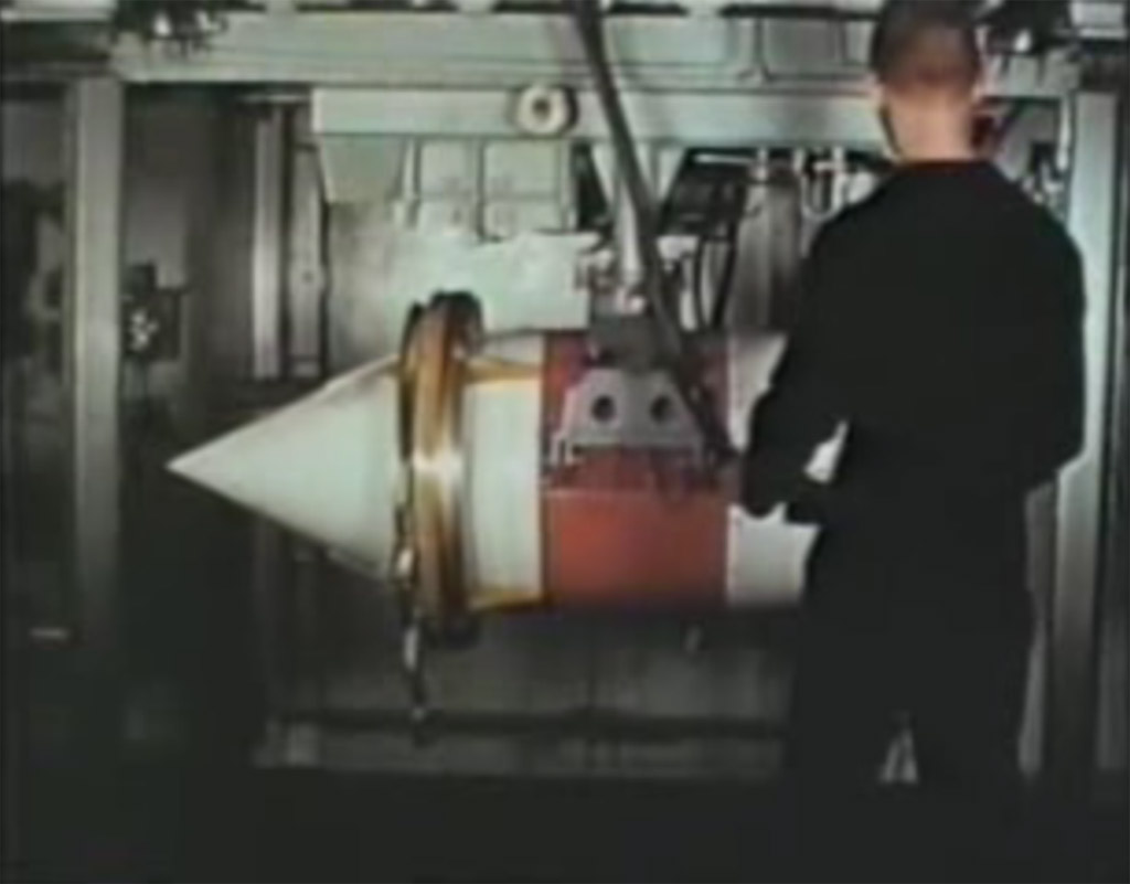
When the Area 1 hatch was opened a Warhead Crane descended into the Special Weapons Office and was fastened to the carrying brackets on the side of the warhead. Then the warhead was released from the Receiving Stand mating bracket and lifted into the Area 1 test cell. There the warhead was rotated horizontal and positioned for mating to a missile. After the warhead was bolted to the missile the crane was released and stowed. The carrying brackets were removed from the warhead, electrical connectors were attached, and the missile cowl was installed.
The process for removing a warhead from a missile and transferring it to the warhead magazine was the reverse of the procedure just described. This was a lengthy procedure, and it was performed only when it was necessary to exchange warheads on missiles stowed in Area 2 or Area 3.
Warheads were received on board the ship on the O2 level top of the missile house. They arrived in large cylindrical shipping containers, or "cans." Cans were positioned with the long axis vertical (flat end down)under a Warhead Davit. The cans were opened and the upper half was removed. A sling was fastened to carrying brackets on the side of the warhead. The sling was attached to a cable from the Warhead Davit that lead to a Snaking Winch on deck. The warhead was lifted from the can bottom and the can was removed. The warhead was then positioned over the Warhead Strikedown Hatch and lowered through the Area 1 Test Cell to a Warhead Receiving Stand waiting in the Special Weapons Office. From there it was moved to the Warhead Magazine by a process that was the reverse of the procedure for raising a warhead from the magazine.
The warhead magazine had an automatic sprinkler system that would flood the magazine with sea water if there was a sudden rise in temperature or pressure. This system was tested periodically. First a baffle inside the fire main pipe was rotated into place and locked to prevent water from passing into the fire main to the magazine. A large fire hose was attached to a fitting in the fire main above the baffle and the other end was attached to a port in the hull. Then a heater was placed against a heat sensor in the magazine, or a pressure sensor was actuated manually. This tripped the magazine sprinkler valve allowing water to flow to the baffle, through the hose and then overboard. After water had flowed for a few seconds the magazine sprinkler valve was closed manually. When the system had drained and the sensors were reset the baffle was moved back to the normal position and locked in place.
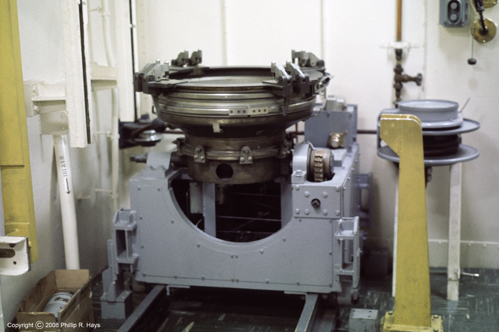
Missile Launcher
The Mk 7 Missile Launcher had two launching rails. It rotated and elevated to aim the missiles in the direction of the intercept point prior to launching. On the rear end of each side was an emergency igniter. This was located on top of the launcher "arm." If a booster failed to fire the igniter mechanism was rotated into position behind the booster and the igniter cartridge was extended into the cavity inside the booster behind the solid rocket fuel. The emergency igniter was rotated back to the position above the launcher arm, uncoiling the ignition wire to the cartridge. Then the igniter cartridge was fired to launch the missile. Another alternative if a booster failed to fire was to wait 30 minutes to be sure it was safe. Then the dead bird could be withdrawn into the missile house for inspection and repair.
The launcher carried electrical contact "shoes" that mated with connectors on the missile and booster firing circuits. A contact shoe extended to make electrical connections to missiles on the rails. When the missile was run out on the rail the electrical contacts provided power to warm up the missile. Early versions if the missiles used vacuum tubes that had filaments that must be heated in order for the circuits to operate. Power had to be supplied for a period while the tubes warmed up. The missiles also carried mechanical gyros that had to be "spun up" to the proper rotating speed before the missile was launched. The missiles carried thermal batteries that contained a solid electrolyte while in storage. When it was certain that the missile would be launched a "candle" in the battery would be lighted to melt the electrolyte. When fully molten the batteries provided power for the launch and operation of the missile. Then the missile electrical contact shoe was raised into the launcher arm.
When all circuits in the missile were ready for operation a rod extended from the launcher and mechanically rotated the booster igniter mechanism from the unarmed position into firing position, opening a path from the igniter to the booster fuel. The launcher made electrical connections to the booster firing circuits. An electrical signal ignited the booster to launch the missile. After the thermal batteries were activated the missile could not be brought back into the missile house while the batteries were warm. It was necessary to wait until the batteries cooled, a half hour or more, before the missile could be taken back inside. The battery had to be replaced before the missile could be fired.
The launcher was manufactured by the same company that built the hydraulic equipment in Area 3, and it suffered from the same seal failure. Consequently, whenever the launcher was powered hydraulic fluid sprayed and dripped everywhere inside. The standard launcher repair equipment kit included a rain coat and an umbrella.