
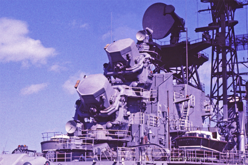
The USS Oklahoma City carried two SPG-49 tracking radars for the Talos missile system. They were part of the Mk 77 Missile Fire Control System. The main component of the tracking radars was the AN/SPG-49 antenna. It was a huge collection of transmitters and receivers, wave guides, antenna components, electrical cables and cooling systems all packed into a 19 foot high by 17 foot wide moving platform that weighed 22 tons. Like everything else in the Talos system it used the most advanced technologies available at the time. It was the Navy's longest range and highest resolution tracking radar.
The 49s had C band monopulse tracking radars and continuous wave (CW) illumination radars combined into the one antenna. The system performed three functions. During target acquisition the antenna radiated widr angle 3 megawatt pulsed bearing and azimuth sweeps to determine range, bearing and altitude of a target. After the target had been acquired the antenna switched to a pulsed 3 megawatt narrow beam tracking radar. When a missile closed range to a target the antenna also radiated a 5 kilowatt CW illumination beam that carried target identification information for the missile to home on.
SPG-49 System Operation
The ship's Combat Information Center (CIC) tracked all airborne targets that were detected by the ship's SPS-43 air search radar. If CIC decided a target was was a threat they sent the target range and bearing to Weapons Control.
The Weapons Control Center in the after superstructure above the missile house and below the AN/SPG-49 antennas operated the Talos missile battery. The SPS-30 3D radar was used to track the target and determine range and elevation. The target was then assigned to one of the two SPG-49 radar systems.
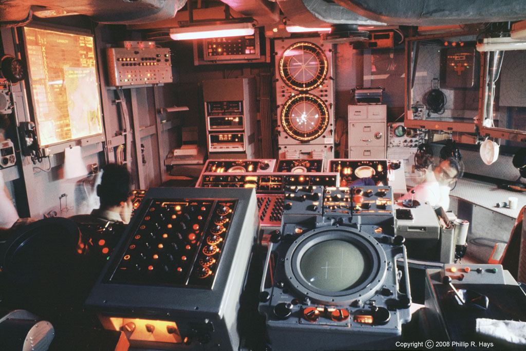
Each SPG-49 radar had its own control room located deep in the ship above the Mk 111 missile fire control computer room. There were two options for the 49s to acquire the target. The operators in the SPG-49 control room could use the Acquisition Console to find the target. The Acquisition Console operator used a joystick on the console to turn the antenna to the direction of the target. The acquisition display had a five level display to show the three dimensional elevation and range of targets in the acquisition search area. When the target was located the bearing, range, and elevation were passed to the Tracking Console operator.
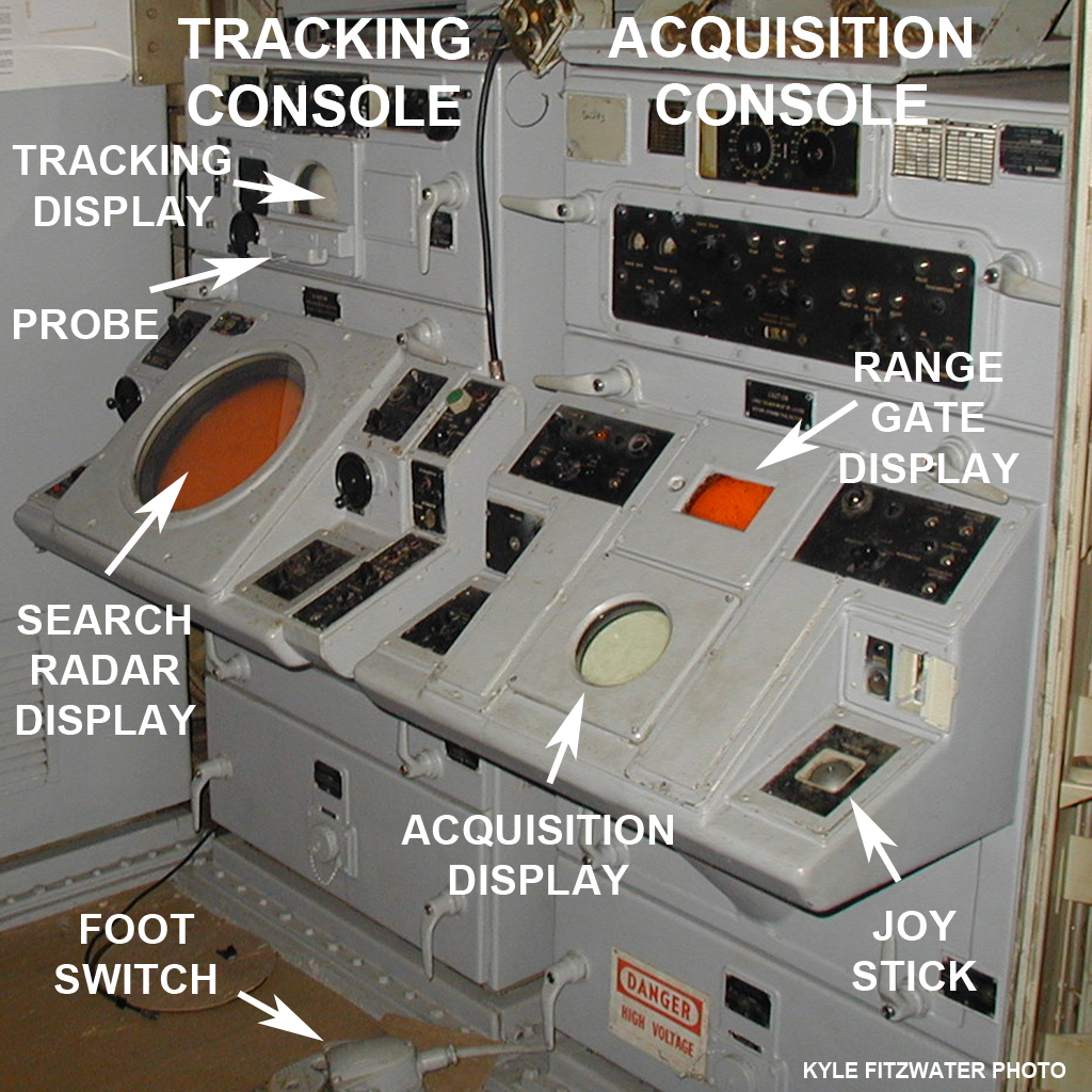
The operator at the SPG-49 Tracking Console in the control room located the target on a search radar display on the Tracking Console that showed target bearing and range. He steered the AN/SPG-49 antenna to the bearing and elevation of the target using hand controls on the console. The operator then watched a tracking display that showed images of all targets along the radar beam axis. The radar had a 10,000 yard (5 miles) range window. The operator used a probe to move the range window along the beam to select the desired target on the screen, and then pushed a foot switch to initiate target lock on and tracking. Target range, elevation and bearing information were sent to the Mk 111 missile fire control computer so it could calculate a missile intercept trajectory. In actual practice the Acquisition Console wasn't used much. An experienced Tracking Console operator could locate the target as fast as the Acquisition Console.
Circuits in the AN/SPG-49 antenna controlled the motors to keep it aimed at the target. However, the system sometimes lost track and the 49 operator had to select the target again. He used the hand cranks on either side of the search display to move the director up/down and left/right to put it on target. Then he would select the target on the tracking screen. A good operator could keep the system on track even if the radar was being jammed. However, if the system could not maintain a range lock on the target the computer switched the missile's trajectory to follow the tracking beam to the jamming signal.
The Mk 111 computer followed progress of the missile with signals from the SPW-2 guidance radar. When the missile neared the target the computer switched on the illumination transmitter for the AN/SPG-49. The computer calculated the Doppler shift due to the relative motion between the target and the ship, and also calculated the Doppler shift between the missile and target. It computed the resulting frequency of the radar echo from the target to the missile. This information was encoded in the illumination signal from the AN/SPG-49. This caused the missile to home in on only that specific frequency, making it impossible to jam the missile. In fact, the missile scored higher success rates against jamming targets than for targets that weren't trying to jam it!
Components Of The AN/SPG-49 Tracking Antenna
The 49s had four major subassemblies, the base (pedestal), the yoke (train member), the elevation gimbal and the antenna (traverse member).
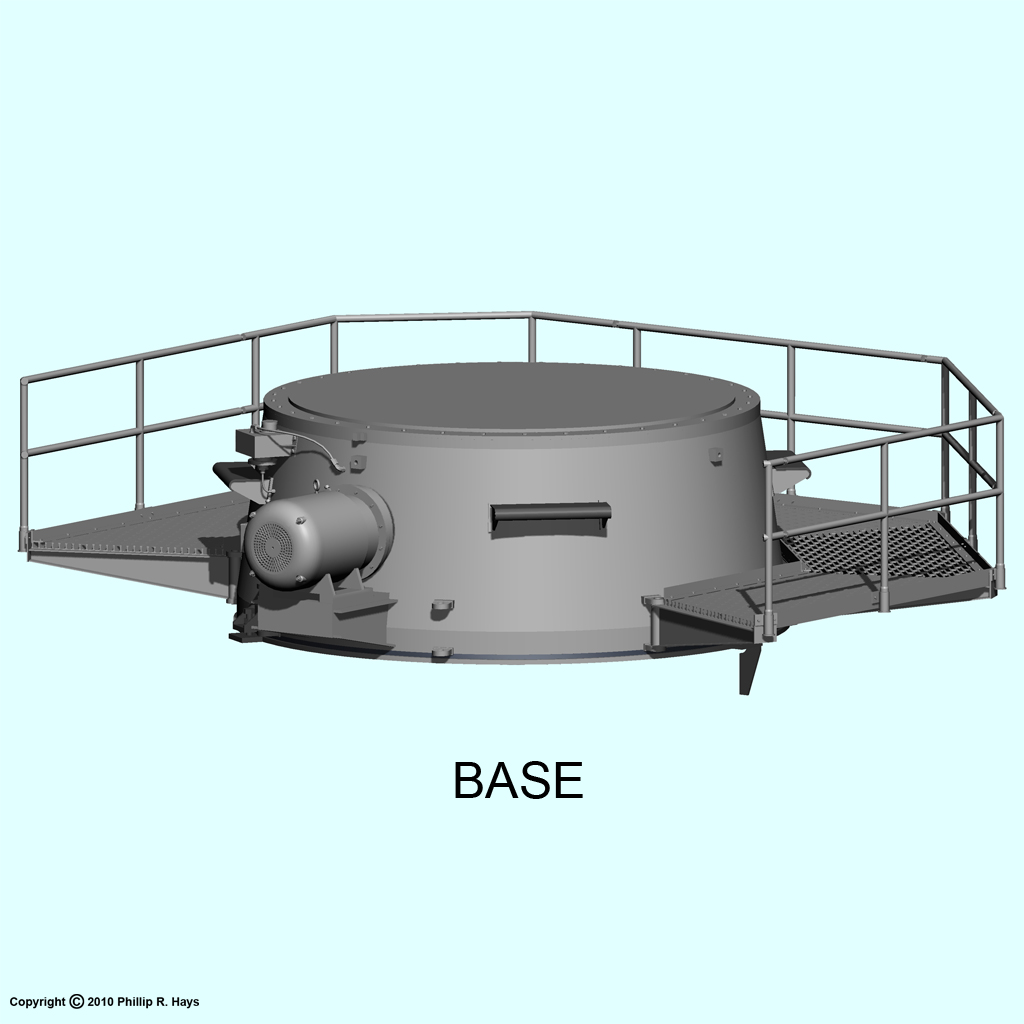
The base or pedestal supported the antenna assembly. It was a truncated cone 9 feet diameter at the base and 41 inches high that was designed to mount on existing Mk 37 gun director barbettes. It was mounted on a barbette in the after superstructure. The upper parts of the antenna rotated around the vertical axis on a roller bearing assembly in the base. A large electric motor drove a hydraulic transmission to turn a train drive pinion gear that rotated the yoke. The base was mounted on a steel ring attached to the barbette. This ring was machined in place with tolerance less than 0.035" vertical. This put the antenna a precise distance above the line of motion (missile plane) of the missile along the transfer rails and onto the missile launcher.
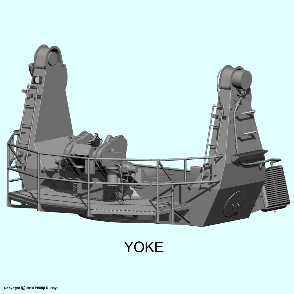
The "U" shaped yoke was 9 feet 1 inch from the base to the centerline of the pillow block bearing supports at the top, and 16 feet wide. It contained a circular train drive "bull gear" that was driven by the train drive pinion gear in the base. The yoke rotated 360° around the vertical axis, and could rotate the 22 ton antenna 180° in 3.5 seconds. An electrical assembly suspended below the yoke contained slip rings that made electrical contact between the rotating antenna assembly and the stationary components in the antenna barbette. The pump, radiator and fan for the antenna's liquid cooling system were mounted on the yoke. Flexible connections carried the cooling fluid to electronics in the antenna. A control box on the yoke opened the doors at the rear of the antenna assembly. The yoke contained two elevation drive electric motors to move the gimbal.
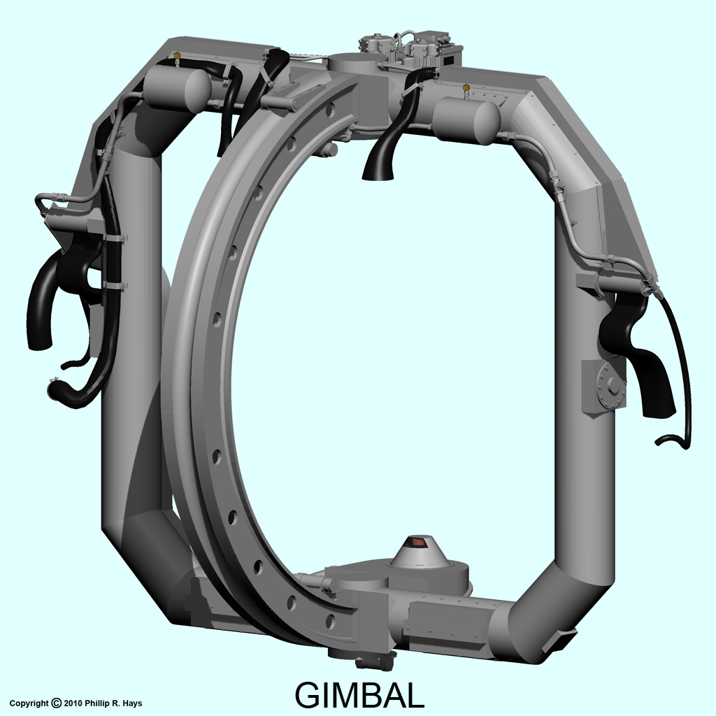
The gimbal was a rectangular frame of 15 inch diameter steel tubing, 12 foot 3 inch by 13 foot 2 inches, that pivoted around the horizontal axis on sleeve bearings in pillow blocks on the yoke arms. A "C" shaped elevation sector gear on the gimbal was driven by the elevation motors on the yoke. The gimbal rotated in elevation -20° to +115° and could rotate 90° in 4 seconds. Fluid reservoirs for the cooling system were mounted at the top of the gimbal. The gimbal supported the antenna traverse frame on upper and lower bearings, and housed the upper and lower pairs of traverse drive electric motors. Each of the four motors had a separate gear train.
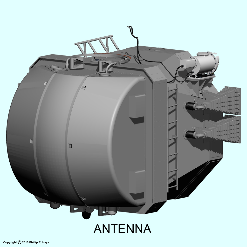
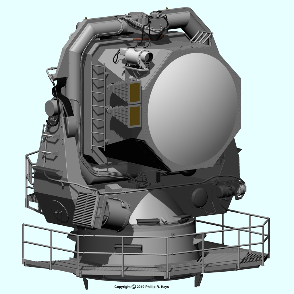
The antenna elements were supported by a traverse frame 9 feet 8 inches wide, 9 feet 1 inch high and 14 inches thick. Arc sector gears mounted on the top and bottom of the traverse frame were driven by the traverse motors on the gimbal to rotate the frame about the vertical axis. The traverse motors moved the antenna rapidly from side to side ±24° at 30° per second without having to rotate the entire massive yoke and gimbal. Attached to the front of the traverse frame was the support frame for the octagonal lens. A rear housing supported two "clam shell" doors that opened to allow access to the interior electronics for maintenance. The electronics were housed in cabinets attached to the frame inside the antenna shells, with a tubular frame to support the microwave plumbing.
The traverse, elevation and train drives all had dual motors with one unit driving and the other providing a low torque opposing force to reduce backlash. Each axis also had a hand crank to allow manual positioning while running bore sight alignment or maintenance. All of these moving elements had associated position transducers, tachometers and switches to provide feedback to the motor control circuits in the antenna and to the Mk 111 computer. The electronic equipment and motors all had power cables, and all of these signal and power connections had to pass through flexible connections at each axis. The whole assembly was covered with cables.
A Mk 12 Mod 0 closed circuit television camera with a Mk 7 Mod 0 lens system was mounted at the top right side of the antenna housing. The camera allowed visual observation of targets and missile intercepts on short range shots. It was also used to locate benchmarks and antennas on the fantail for transmitter tests and to help locate collimation towers on shore for system alignment in port.
Subassemblies In the Antenna
NOTE: The illustrations of the interior parts of the antenna are just conceptual drawings. I have only very general diagrams of some of the parts and other drawings are based upon similar antenna systems. The relative dimensions are purely speculative. Left/right orientation is looking from the back of the antenna in the direction the antenna pointed.
The AN/SPG-49 was unusual because much of the electronics were enclosed within the antenna shell, instead of below decks inside the ship as with most other tracking radars. The internal components were accessed through two large clamshell doors at the rear of the enclosure.
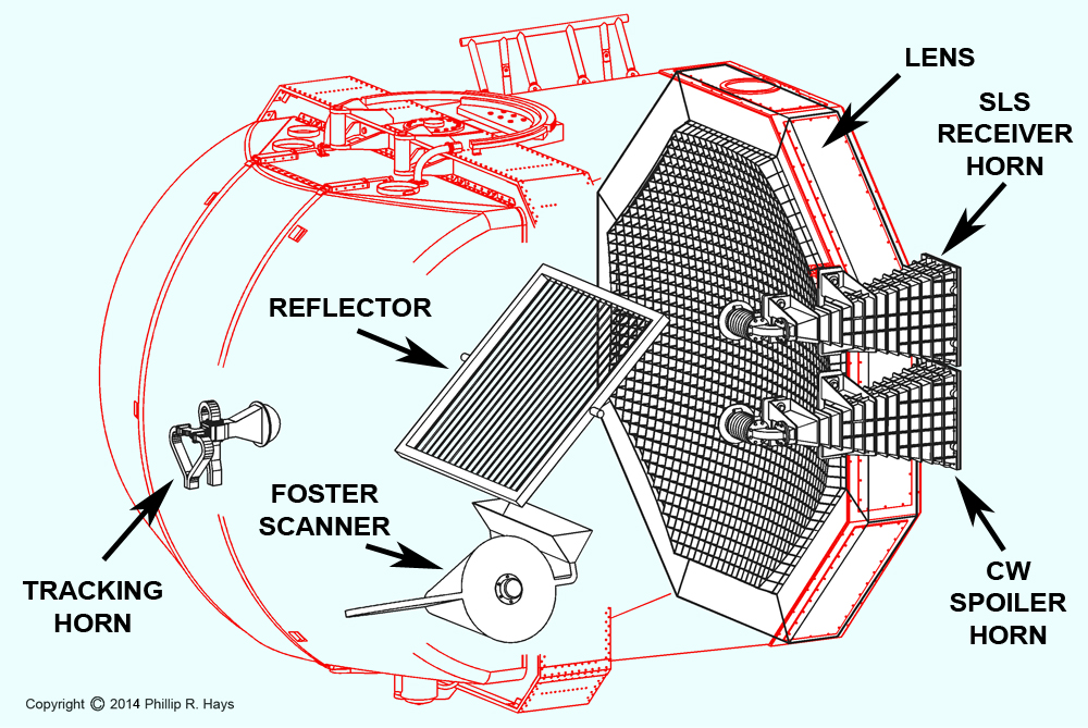
The antenna contained transmitters, receivers and associated antennas, microwave plumbing and electronics for the radar system. Waveguide switches allowed transmitter output to be sent through additional waveguide plumbing to dummy loads and RF test points. Because of the high signal power levels the waveguide plumbing was pressurized with dry nitrogen to prevent arcing. Pressure sensitive interlocks would shut down the transmitters in the event of loss of pressurization.
The arrangement of the main components of the AN/SPG-49 antenna are shown in the diagram. The tracking horn sent out microwave pulses and received the return signal from the target. The Foster scanner generated both the pulsed acquisition signals and the continuous wave (CW) illumination signals. The reflector directed the signals from the Foster scanner out through the front of the director toward the target. The microwave lens focused returning radar reflections from the target onto the tracking horn and Foster scanner. The function of each of these components is described in detail below.
Because much of the electronics for the SPG-49 system were packed into the antenna shell it was difficult to service these components during foul weather. The antenna was exposed to the elements and all parts were subjected to humidity, salt air, vibrations and accelerations as the antenna moved to track a target. These effects combined to reduce the reliability of the system.
Transmitters And Waveguide Switches
The 3 megawatt pulsed acquisition and tracking transmitter was located inside the antenna shell. It consisted of a local oscillator, SAC45 amplifier, SAC46 exciter, SAC47 driver, and SAC42 klystron power amplifier. A large oil filled, liquid cooled pulse transformer generated a 3 microsecond 128 Kilovolt pulse to drive the SAC42. The 5 kilowatt illumination transmitter was also inside the antenna shell. It used a klystron operating in continuous wave (CW) mode, with the output signal routed to the Foster scanner.
During acquisition the output of the 3 megawatt pulsed transmitter was routed through two waveguide switches to the Foster scanner. The rotating scanner deflected the pulsed beam about ±5° to produce a wide sweep.
After the target was acquired the 3 megawatt pulsed beam was directed through a waveguide switch to the tracking horn.
When the Mk 111 missile fire control computer was ready to tell the missile to home on the target it turned on the 5 kilowatt CW transmitter and routed the beam through a wave guide switch to the Foster scanner. At this time the scanner was not rotating but was positioned so the CW beam would be coaxial with the 3 megawatt tracking beam.
Tracking Horn
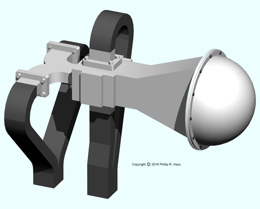
These images of the tracking horn are based upon the assembly in the AN/FPS-16 tracking radar. Some sources say some of the components of the SPG-49 were originally developed for the FPS-16, or perhaps the mobile AN/MPS-25 version of the FPS-16. However, the AN/FPS-16 and the AN/MPS-25 were single beam radars with large parabolic reflector antennas that looked nothing like the AN/SPG-49. The AN/SPG-49, AN/FPS-16 and AN/MPS-25 radars were all developed by Sperry Rand Corporation.
The assembly shown at left had a dome cover on the front of the antenna horn and four waveguides leading from the horn to the transmitter and receiver electronics. The dome was transparent to microwave energy and sealed the waveguide system that was pressurized with dry nitrogen. The horn itself had four chambers, as shown at the right. Internally it was constructed so the the signals entering the top two chambers combined to generate the A+B output and the lower two signals combined to produce the C+D output. Only part of the energy was transferred to the up/down signals. The remaining energy produced the left/right signals. The left two signals combined to make the A+D output and the right two signals created the B+C output. In addition, the waveguide design behind the horn caused the complimentary left/right and up/down signals to be 180° out of phase with each other. All of this was accomplished with waveguide impedances that didn't introduce thermal noise into the signal like a bunch of resistive electronic components would do. This waveguide magic was brand new bleeding edge technology when the AN/SPG-49 was being designed.
Microwave signals from the transmitter were injected into the rear of the horn through the left/right waveguides and the energy exited all four cavities at the front of the horn. The taller than wide horn mouth caused the beam to be relatively thin vertically but broader horizontally. This was the optimum configuration for a long range tracking radar where the target bearing would change more than the elevation.
Variable Path Scanner
For target acquisition it was necessary to sweep the radar beam through a wide angle horizontally. The desired sweep rate was too fast to oscillate the entire antenna so it was necessary to use some other mechanism to sweep the beam.
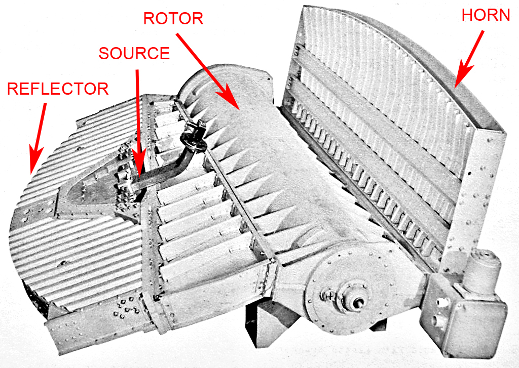
In 1945 J. S. Foster at Massachusetts Institute of Technology Radiation Laboratory invented a novel way to deflect a microwave beam from side to side without moving the antenna. His variable path length Foster scanner has been used in many tracking radar applications, and was the basis for the AS-782/SPG-49 acquisition system traverse scan mechanism in the AN/SPG-49. Microwave energy was admitted at the source position in the picture. It reflected off the parabolic reflector and flowed through a broad wave guide to a rotating rotor. After passing around and through the rotor the beam followed a wave guide to a folded reflector transmitting and receiving horn.
Microwave energy was delivered through a 2 inch by 1 inch wave guide (the source) and flowed into a 1 inch high E-plane cavity in the "pillbox" reflector. It reflected off the parabolic end back toward the scanner mechanism as a plane wave. The wave guide thickness tapered to 1/2 inch at the exit of the pillbox where it joined a wedge-shaped waveguide section. The tapered wedge steered the wave front 4° so it entered the scanner at an angle. This caused the wave exiting from the scanner to be scanned equally to either side of a line perpendicular to the rotation axis of the scanner.
The rotor was a truncated cone in shape, with the small end 7 1/2 inches diameter and the large end 9 1/2 inches diameter. It fit inside the surrounding shell. The 1/2 inch space between the rotor cone and the shell formed the E-plane dimension of a curved waveguide for the microwave radiation. The rotor had a channel across the diameter that also served as a wave guide. The geometry of the rotor and waveguide assembly determined the scan angle and the speed of rotation determined the scan rate.
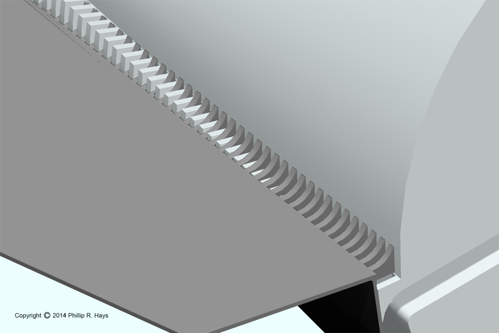
Microwave energy was reflected into the cavity between the shell and rotor and back out to the exit waveguide by projections on the shell and rotor. These projections were like the teeth of a comb, with the teeth on the rotor passing between the teeth on the shell, with a 0.030 inch gap that allowed full rotation of the rotor. They were spaced at less than half a wavelength of the microwave energy so they served as an almost perfect reflector. First the comb on the shell at the entrance to the scanner reflected energy into the space between the rotor and shell. Then teeth on the rotor deflected the energy through the central passage in the rotor. At the other end of the central passage the energy was reflected into the cavity between the rotor and shell again, and teeth on the shell at the exit of the scanner directed the energy out of the scanner into the attached waveguide.
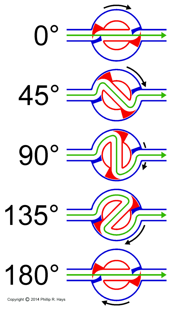
The basis of operation was the variable path length created by the rotating rotor. The diagram shows the result of rotation on the path length (green line). When the channel in the rotor was aligned with the waveguides to either side (0°) the microwave energy passed straight through. As the rotor turned through greater rotation angles the path length increased, becoming greatest just before 180° rotation. At 180° the channel in the rotor again lined up with the waveguides and the energy flowed through in the shortest path again. The result was a sawtooth-type scan.
The channel around the rotor varied in length with the diameter of the conical rotor. The path around the narrow end was shorter than the path around the wider end. Consequently, it took longer for the energy to pass around the wider end, and less time around the narrow end. Energy entering the rotor section had a wave front aligned at an angle to the axis of the rotor. If the rotor was rotated 0° the wave front passed through with no deflection because all parts of the beam traveled the same distance, so the wave front was deflected to one side in the horn.
But when the rotor was rotated each part of the beam traveled a different distance. This caused the wave front to be skewed at an angle to the wave guide axis. The configuration of the rotor and wave guides was such that at 0° rotor rotation the beam was deflected 5° to one side, at 90° rotation the beam passed straight out of the horn, and just before 180° the beam was deflected 5° to the opposite side. When the rotor reached 180° the beam deflected back again to start the sequence over. It was a combination of the different path lengths around different sections of the conical rotor and the varying path length as the rotor turned that caused the wave front to be deflected through a wide angle.
The exiting wave guide and acquisition horn contained a diverging lens to focus energy from the four foot wide horn onto the reflector and then to the eight foot wide lens. The entire acquisition assembly was pressurized with dry nitrogen to keep out moisture.
Reflector
The AT-636/SPG-49 reflector was a frame with a vertical rod grill. The rod diameter was about 1/32 of the wavelength and 1/8 wavelength spacing to be transparent to waves polarized with the electrical field perpendicular to the rods, but to be a reflector for waves with an electrical field polarized parallel to the rods. The signal from the transmitting horn at the rear of the antenna was polarized to pass through the reflector. The signal from the acquisition horn below the reflector was polarized so it would be reflected by the reflector. This allowed the two signal sources to reside within the one antenna assembly.
The reflector was tilted at approximately 45° to both the acquisition and tracking signals. It rotated around the horizontal axis so it could tilt through a range of angles to deflect the beam from the acquisition horn at different elevations during acquisition mode.
Microwave Lens
At the front of the antenna was an octagonal AT-828/SP microwave lens. It was protected by a RF-60/SPG-49 fiberglass dome. The lens focused transmit energy from the tracking and acquisition horns into a narrow beam. Radar reflections from the target were focused into the tracking and acquisition horns. The lens inverted the image. The effect was to project the image of a target that was above the horn axis "upside down" into the horn below the horn axis. Both up/down and left/right inversions occurred.
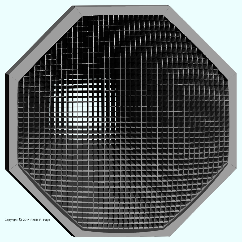
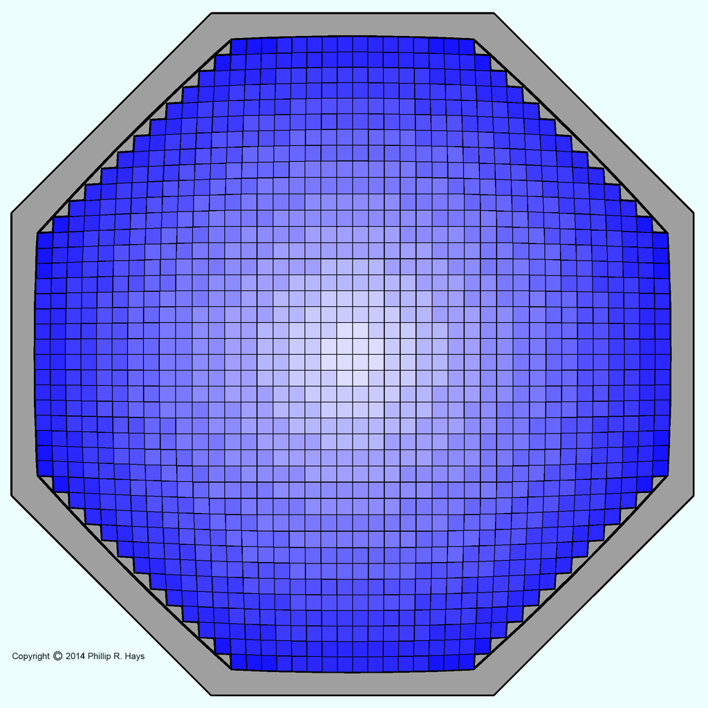
The lens refracted and focused microwave energy similar to how glass lenses focus light. The drawing at the right shows how the lens appeared to impinging radiation. Near the center the waves were refracted very little (light blue), with refraction increasing outward and the greatest effect near the edges (dark blue).
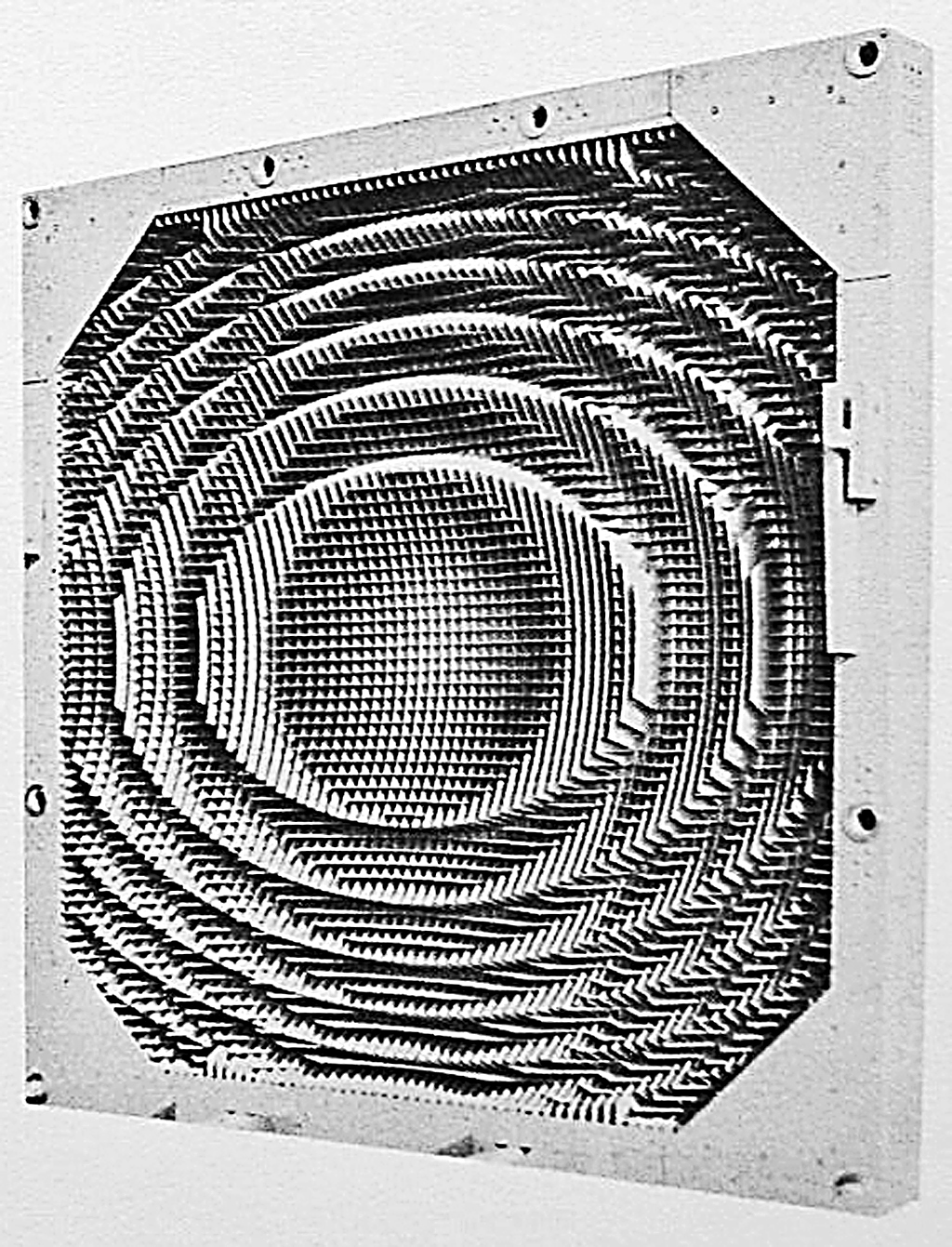
The lens was 110 inches high by 110 inches wide and 31 inches thick. The front of the lens was planar to send and receive planar waves. The rear surface was concave, contoured somewhat like a Fresnel lens, but it was machined with two contours so the one lens could focus energy for the tracking horn and the acquisition horn. The tracking contours were circular and the acquisition contours were approximately elliptical. The two different contours did not interfere significantly with either the acquisition or tracking signals.
The lens was constructed of resin-impregnated fiberglass with silver-plated cells and metallic loading elements. The inside surfaces of the cells had extremely smooth coatings containing suspended particles of conductive materials. Cross section dimensions of the cells were less than half a wavelength so the cells did not function as wave guides. Instead the lens assembly was transparent to the radiation and possessed increasing dielectric constants from the center to the edge. The distance from the center of the lens to the acquisition horn was eight feet, and to the tracking horn was 7.2 feet.
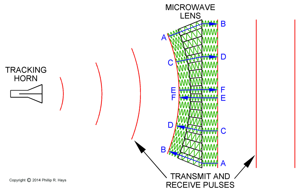
The velocity of phase propagation of the microwave signal was greater in the lens cells than in air. Because of the concave inner surface of the lens the wave guide cells near the center were shorter than those near the edge. Consequently, the outer parts of the waves were accelerated longer than the inner parts. Transmission times A-B, C-D and E-F were equal.
Spherical transmit waves from the horn emerged from the outer side of the lens as parallel planar waves. Likewise, nearly planar reflections from the target exiting the cells from the circular contours combined to form a spherical wave front collimated to focus on the tracking horn. Acquisition transmit waves reflected off the reflector passed through the elliptical contours to emerge as planar waves. The returning planar waves emerging from the elliptical contours and reflected off the reflector were focused on the acquisition horn.
External Horn Antennas
The AN/SPG-49 had two external horn antennas mounted on the outside of the antenna. Neither of these was originally a part of the system, and both were added to correct deficiencies. After the CW illumination mode was added to Talos it was discovered that the radiation pattern from the Foster scanner through the microwave lens had distinct lobes - some areas received a lot of microwave energy and some areas received little. If the target flew through an area with low energy it was harder for the missile to detect the reflected signal and home on the target. The CW spoiler horn was added to transmit part of the CW energy in a broad area to fill in nulls in the primary beam. About 25% of the CW energy was routed through the spoiler horn.
The side lobe suppression (SLS) receiver horn was added to prevent a hostile decoy from deceiving the receiver by transmitting a false target signal into a side lobe of the tracking receiver antenna. The SLS receiver horn was mounted above the CW spoiler horn.
Cooling System
The large SAC42 klystrons in the transmitters were liquid cooled, as were dummy loads and some other parts in the antenna. The coolant was Ambitrol, a glycol based liquid similar to automobile antifreeze.
On the right front of the yoke was a large box containing a radiator attached to a cylindrical fan. The coolant was circulated by a pump on the left front of the yoke. Next to the pump was a round cover over an expansion bladder that allowed for volume changes due to coolant expansion. The coolant passed through a filter on the left side of the yoke and flowed through pipes and hoses up to the gimbal. At the top rear of the gimbal were two coolant reservoirs. From these the coolant flowed through flexible hoses to the top of the antenna. After passing through the hot elements in the antenna the coolant flowed out through the top of the antenna, down through hoses and pipes on the right side of the yoke and into the radiator.
Another smaller radiator and fan were located on the lower left side near the front of the antenna housing. This may have cooled the oil in a high voltage pulse transformer in the antenna.
Operating Modes
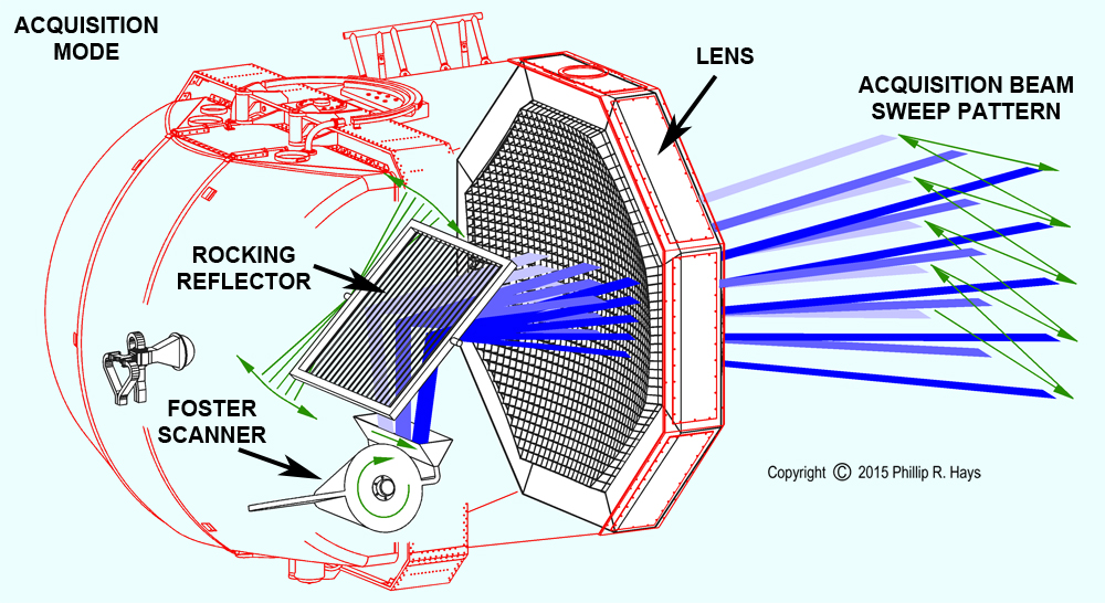
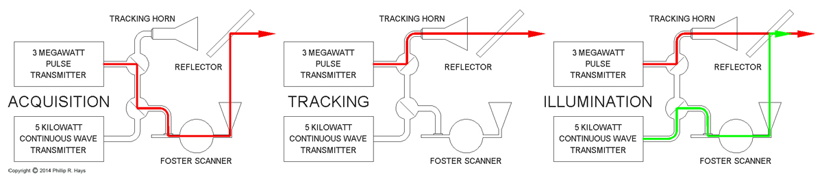
Acquisition Mode
During acquisition mode the Foster scanner produced a scanned 3 Megawatt pulsed beam that reflected off the reflector. The reflector pivoted so the acquisition beam could be swept vertically. The reflector was tilted in increments to generate beams at -2°, -1°, 0°, 1° and 2°. The result was the acquisition beam axis that swept horizontally ±5° and vertically ±2° from the antenna axis.
Tracking Mode
In tracking mode the reflector was locked in place at a 45° angle and the Foster scanner was inactive. The 3 Megawatt pulsed signal from the tracking horn passed through the reflector and was focused by the lens to create a narrow tracking beam. The reflection from the target was focused by the lens on the tracking horn.
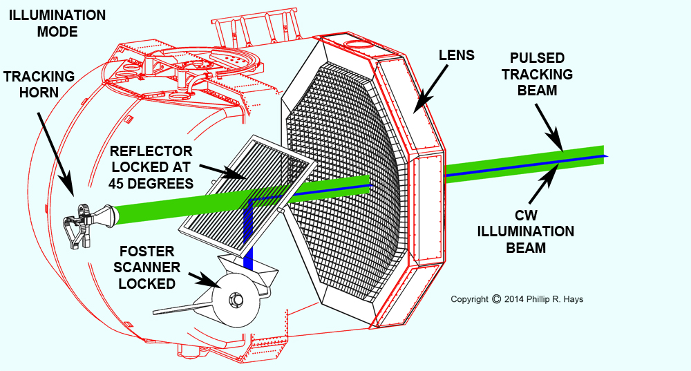
Illumination Mode
During the continuous wave illumination mode the reflector was fixed at a 45° angle and the Foster scanner did not rotate. The 3 Megawatt pulsed tracking signal from the tracking horn passed through the reflector while the 5 Kilowatt continuous wave signal from the Foster scanner was reflected by the reflector to produce a CW beam coaxial with the tracking beam.
Monopulse Radar
Radars are used for both searching and tracking a target. Search radars look in all directions to detect targets. Many have a rotating antenna that sweeps the radar beam around the horizon. Targets send back a return only for the brief instant the antenna is pointed in their direction. This allows detection of a target but isn't useful for continuous tracking to calculate fire control solutions. And most search radars don't produce elevation information.
Tracking radars are pointed in the direction of the target, providing continuous target range, elevation and bearing information. One form of tracking radar used a rotating feed horn to generate a conical scan - similar to the conical scan of the SPW-2 guidance antenna. With conical scan systems the antenna position gives the bearing and elevation to the target and the strongest return signal occurs when the antenna is pointed directly at the target. If the target changes direction and moves off axis the signal weakens. Several successive conical scans are needed to detect the signal strength drop off, causing a slight delay in detecting maneuvers by the target. When this happens the entire antenna is repositioned to increase the signal strength. When the signal strength reaches a maximum the antenna is again aimed at the target, but it is necessary to search back and forth past the target to determine just where the signal reaches maximum, delaying the tracking solution further. However, other factors like clouds, rain, and change of orientation of the target can cause the signal strength to weaken, making it appear the target is maneuvering when it isn't, confusing the fire control solution. Also, conical scan tracking radars can be jammed fairly easily. Some other method to track targets was needed that wasn't susceptible to variations in signal strength and jamming.
Monopulse radars are not susceptible to the problems of conical scan radars and can determine bearing and elevation much quicker. They broadcast a series of pulses and calculate target position from the return echo of each pulse. The tracking horn is fixed along the axis of the antenna (the beam axis). It is divided into multiple chambers and the return signals entering these chambers are compared to determine elevation and bearing to the target. Only the relative signal strengths of the return signals matter, so environmental conditions that affect signal strength do not influence the tracking solution.
One of the more interesting things about how the AN/SPG-49 antenna worked is that signal pairs were summed in the tracking horn. This was a function of the waveguide geometry inside the horn. First, part of the energy in the upper and lower pairs of signals was summed, and this energy went into the A+B and C+D waveguides. The remaining energy in the left and right signal pairs was summed and this energy went into the A+D and B+C waveguides. The design of the horn also caused the opposing signal pairs to be 180° out of phase with each other. The waveguides fed four circuits in the receiver to produce the electronic signals for the signal processing system.
For each pulse the receivers were switched out of the circuit while the high energy pulse was transmitted through the horn. Then the receivers were switched back into the circuit. The lens focused the outgoing pulse into a narrow beam that reflected off the target. The returning echo signal was focused by the lens onto the antenna horn. If the returning signal arrived off axis of the tracking horn (off to one side, or above or below) it was focused unevenly on the four chambers of the horn. If the target was above the beam axis the returning signal was focused on the lower chambers of the horn. If the target was to the left of the beam axis the return signal was focused into the right side of the horn.
The illustration shows two examples. When the target was high and to the left of the beam axis the lens focused the returning signal to the lower right chamber of the horn. The largest amount of energy entered the C chamber, but B and D also received a significant amount of energy. If the target was to the right and at the same elevation as the beam axis the A and D chambers divided most of the energy but a significant amount was shared equally by B and C. If the target was to the left of the horn axis the B+C signal was stronger than the A+D signal. Likewise, if the target was above the beam axis the C+D signal was stronger than the A+B signal. The farther the target was off center from the beam axis the greater the difference between opposite signal pairs A+B/C+D and A+D/B+C.
The four signals (A+B, C+D, A+D and B+C) were also combined (without phase inversions) to create a return timing pulse. The time delay between the transmitted pulse and the return pulse told the distance (range) to the target. The Mk 111 computer used the range, traverse and elevation information to generate a running calculation of the target's position. This information was used to compute the intercept point and flight path for the missile. While the missile was in flight the computer drove the AN/SPW-2 guidance antenna to steer the missile to the target and initiate the homing sequence.
Now let's look at how the signal processor used this information to generate drive signals for keeping the antenna aimed at the target. The up/down and left/right signal pairs were combined in the receiver's signal processing circuitry. Because the antenna horn waveguide geometry caused the A+D and B+C signals to be 180° out of phase with each other, combining them subtracted A+D from B+C [(B+C)-(A+D)] to generate a traverse error signal. If B+C was larger than A+D the sum would be positive, and if A+D was larger the sum would be negative. In the same manner A+B and C+D were combined [(A+B)-(C+D)] to generate an elevation error. If A+B was greater than C+D the sum would be positive, and if C+D was greatest the sum would be negative. These error signals were generated inside the antenna unit and drove drove motors in the base, yoke and gimbal to reposition the antenna so the beam axis pointed at the target. A positive traverse signal caused the antenna to be turned to the left, and a positive elevation signal caused the antenna to be rotated down. When all four signals (A+B, C+D, A+D and B+C) had the same signal strengths the antenna was aimed directly at the target.
A feature of monopulse systems is the antenna doesn't have to be pointed directly at the target to get useful tracking information. The antenna had a relatively wide "aperture" that allowed tracking to continue if the target changed course. Control circuits in the antenna turned it to keep the target in the beam and maximize signal strength.
The SPG-49 generated a 3 microsecond pulse, and 450 pulses per second. It was a C band radar with a nominal frequency of 5.6 GHz. It had a maximum range of 300,000 yards or 150 nm. It had a 0.25 milliradian tracking resolution. To test the system a six inch diameter aluminum ball was launched beneath a weather balloon and tracked. The 49s could track the 6 inch diameter target sphere to beyond 55 miles (110,000 yards).
Pulse Compression
Pulse compression is a technique for improving the accuracy of the measurement of the distance to a target and improving the signal to noise ratio in a pulsed radar system. It was used in the SPG-49 tracking radar to improve the accuracy of the intercept calculations.
In a pulsed radar energy is radiated as short bursts, or pulses, of a sinusoidal wave at the designed frequency of the system. Longer pulses contain more energy, making the return signal from the target easier to detect. However, the longer the pulse the more ambiguity there is in the calculated range to the target. All that can be determined is that the target is somewhere within an area the length of the pulse. This is especially a problem if two targets are physically separated by a distance less than the pulse length because they will appear as a single target. A 3 microsecond pulse is about a half a mile long, so the radar wouldn't be able to distinguish targets less than half a mile apart. To increase resolution it is necessary to reduce pulse width, and that reduces the intensity of the returned signal making it harder to detect a target.
Pulse compression allows higher resolution with longer pulse widths, improving both the accuracy of the distance measurement and return signal strength. The pulse is generated by varying the frequency of the sinusoidal signal (frequency modulation) during the pulse duration. A pulse typically starts at a frequency lower than the nominal frequency of the radar and sweeps linearly to a higher frequency, with the nominal frequency at the center of the pulse. This is known as "chirping." The energy in the frequency modulated pulse is approximately equal to the energy in a single frequency pulse of the same duration.
The returning echo from the target was cross-correlated with the original transmitted pulse through a matched filtering process. The returning pulse was run through filters to split it into separate narrow frequency bands. These were fed into a series of delay lines that caused all sub pulses to stack up into a single large narrow 0.3 microsecond pulse. This gave a range resolution of about 300 feet. In addition the process filtered out most background noise in the received signal, improving the signal to noise ratio.
The SPG-49 used a 10:1 frequency modulated sweep (chirp) ±5% of center frequency, or 5.3 to 5.9 GHz. The 3 microsecond swept pulse gave a resolution equal to a 0.3 microsecond fixed frequency pulse with the energy of a 3 microsecond fixed frequency pulse.
Parametric Amplifiers
The 49s used parametric amplifiers in the receivers. These were switched on for low signal strength. Parametric amplifiers utilize an inherently unstable nonlinear oscillator. An external signal source "pumps" a high powered signal Fo into the oscillator. A weak input signal Fi induces instability in the oscillator causing it to transfer energy from the strong oscillator signal Fo to the weak input signal Fi, resulting in an amplified input signal. The output of the amplifier contains the sum (Fi+Fo) and difference (Fi-Fo) of the two signals.
The gain of the amplifier is the ratio of the output frequency to the input frequency. The gain of the sum signal is (Fi+Fo)/Fi and the gain of the difference signal is (Fi-Fo)/Fi. Since Fi+Fo is greater than Fi-Fo the sum signal is the strongest. The sum signal is an amplified version of the original input signal so it is chosen as the output from the amplifier.
Parametric amplifiers are very sensitive for weak signals. This method of amplification generates no thermal noise so it introduces very little noise into the signal.
References
1. Antenna Catalog, Volume III, Ship Antennas, Electronic Research Directorate, Air Force Cambridge Research Laboratories, Georgia Institute of Technology Engineering Experiment Station, October 1960.
2. A Textbook of Radar, Commonwealth Scientific and Industrial Research Organization Radiophysics Laboratory, Chapman & Hall, 1948.
3. NOLTR 62-102, The Nature of Microwave Parametric Amplification, United States Naval Ordnance Laboratory, White Oak, Maryland, 5 September, 1962.
4. NAVORD OP 3308 Second Revision, Department of the Navy, Bureau of Ordnance, page 3-6.
5. Radar Handbook, Merrill Skolnik, McGraw-Hill Education, 3rd Edition, February 12, 2008.
6. BUORD OD 9176, Radar Set AN/SPG-49, Volume 1, Description, Operation, Adjustment, Department of the Navy, Bureau of Ordnance, August 1953.
7. BUORD OD 9176, Radar Set AN/SPG-49 (XN-1), Volume 2, Theory of Operation, Department of the Navy, Bureau of Ordnance, August 1953.
8. BUORD OD 9176, Radar Set AN/SPG-49 (XN-1), Volume 3, Theory of Operation, Department of the Navy, Bureau of Ordnance, August 1953.
9. BUORD OD 9543, Radar Set AN/SPG-49 (XN-2), Volume 1, Introduction, Physical Description and Functional Description, Department of the Navy, Bureau of Ordnance, 22 March 1955.
10. BUORD OD 9543, Radar Set AN/SPG-49 (XN-2), Volume 2, Installation and Adjustment, Operation, and Maintenance, Department of the Navy, Bureau of Ordnance, 22 March 1955.