
This is a history of the development of the ramjet engine for the Talos missile. The ramjet was chosen to power the new missile because at that time (1945) rockets did not have long enough range and did not carry a large enough payload. Turbojets were in their infancy and were still subsonic. It was thought the ramjet might operate at supersonic speeds for long ranges.
Will it work?
When the Bumblebee program started no one had ever flown a supersonic ramjet powered missile. The initial goal was to determine if a ramjet (also known as an athodyd, for aero-thermo-dynamic-duct) would work to propel a missile, or prove why it wouldn't. Almost everything about the ramjet engine had to be developed from scratch, with little prior knowledge or experience to work from.
The earliest ramjet design was created by a French mechanical engineer, Rene Lorin. In 1909 he proposed using a jet engine to power a guided "aerial torpedo" to defend against German airplanes. He published his theoretical ramjet design in 1913. Another Frenchman, Rene Leduc tested a small ramjet and applied for a patent in 1934. In 1936 F. W. Meredith of the RAE Farnborough, U. K., had noted that some thrust is created in engines that produce a heated exhaust that is at higher pressure than the ambient air, but this conversion of heat to thrust was insignificant in the piston engine aircraft of the time.38 However, the radiator of the P-51 Mustang used the Meredith effect, and the thrust generated from the heated air was equal to about 88% of the radiator drag, significantly improving the performance of the airplane.
In 1941 researchers at NACA (National Advisory Committee for Aeronautics) tested the Meredith effect in a high-speed wind tunnel, using 160 KW electrical heaters in an 11 inch diameter propulsive duct. They achieved thrust equal to drag at about Mach 0.5, and net positive thrust at Mach 0.75, proving the Meredith effect was real, and also demonstrating the basic principles of operation of the ramjet engine. The heaters generated more heat than an equivalent piston engine, but produced far less heat than would be released by burning kerosene.26 Most people in the aviation industry believed that jet engines could never produce as much thrust as a propeller, so this work was ignored until 1943 when U.S. Navy researchers were looking for ways to power missiles. Their report, "Performance of Open Duct Propulsion Systems (Ramjets) at Subsonic Speeds," was the seed for further research by Johns Hopkins Applied Physics Laboratory.
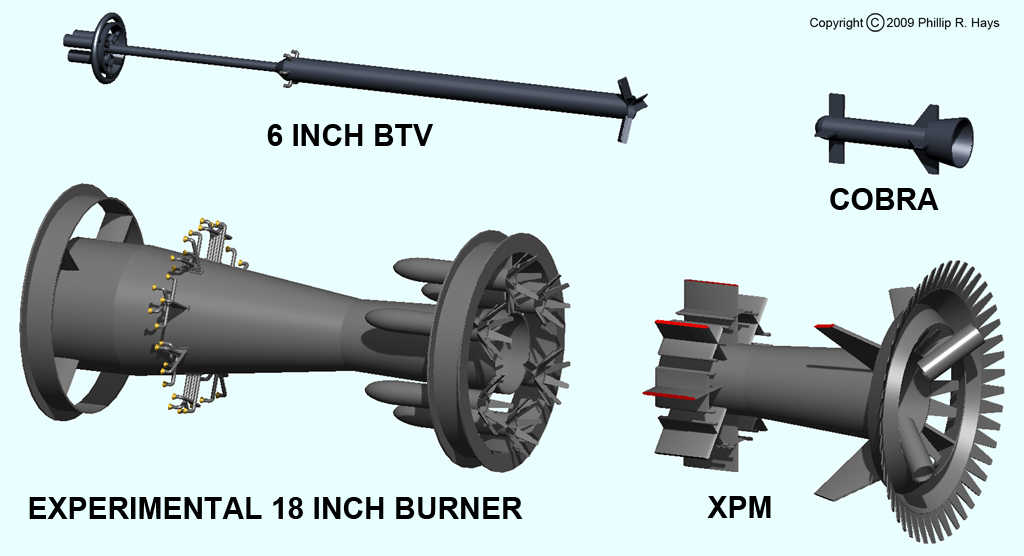
The ramjet engine is called a "burner," and the early experimental units were called burner test vehicles (BTV). The first prototype designs were made from a 6-inch diameter tail pipe from the P-47 Thunderbolt fighter - they were the only stainless steel tubes available at the time.51 The prototypes were just open pipes with a fuel sprayer and a tracer flare from an antiaircraft shell to keep the fuel ignited. It was necessary to provide a high volume air supply into one end, and then spray in fuel and ignite it.
Early flight tests used clusters of the readily available 5-inch HVAR model 38 "Holy Moses" aircraft rockets as a booster to accelerate the ramjet test vehicles to supersonic speed. The first tests were carried out February 16, 1945, and the first clearly successful test producing thrust at supersonic speeds was on 13 June 1945 with carbon disulfide fuel. The first demonstration of thrust in excess of drag was in October 1945 using heptane fuel.52 These early tests were unguided projectiles fired over the ocean.
In late 1945 the Ramjet Test Vehicle (RTV) was planned. It had an 18-inch diameter engine and was designed to carry guidance equipment and a warhead. It was unable to withstand the stresses produced during operation. The only flight test, in December 1945, used kerosene fuel and produced acceleration of 2.5g and a 2200 fps (1500 mph) maximum velocity.
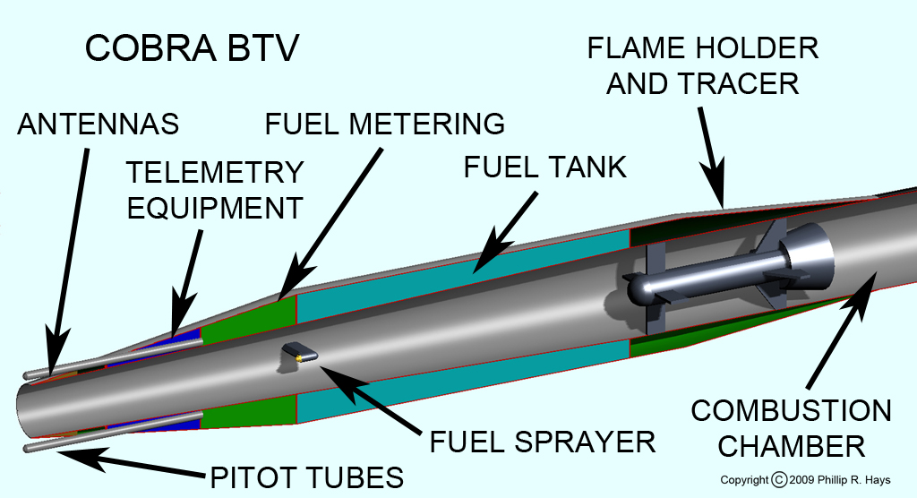
The 6-inch diameter test vehicle design was modified early in 1946 to increase the forward section diameter to 8.5 inches to give more space for fuel, instruments and telemetry gear. The increased diameter added to drag and this reduced the tendency to accelerate to destruction with fuel rich air mixtures. Because of the widened front end the Model 3B vehicle was called "Cobra." It weighed 70 pounds and developed between 2000 and 3000 horsepower, equivalent to a large radial airplane engine.
In 1947 another 18-inch diameter test vehicle similar to the RTV was produced with the warhead and guidance equipment repositioned in a stronger area. This was called the PTV-4 or PTV-N-4 Burner Test Vehicle (BTV) and it was used for additional tests of the ramjet engine.7
The design for a larger Experimental Prototype Missile (XPM) was started in late 1946. It had a body diameter of 28 inches with a combustion chamber 24 inches diameter. The XPM (RTV-N-6a4a or XSAM-N-6) first flew in March 1949. It produced the expected thrust but the engine quit after 7 seconds because of an excessively rich fuel mixture. Subsequent tests were successful. The XPM had a compressor innerbody inside the nose to slow supersonic air to subsonic velocities and a "starting restrictor" grid within the combustion chamber to reduce airflow for ignition. After burning started the restrictor was blown out through the nozzle.
These tests demonstrated conclusively that a ramjet powered missile was possible. However, development of an operational missile was a complicated and drawn out process, and it would be another ten years before the first Talos missiles entered service in the fleet.
Ramjet fundamentals
Initially ramjet engines were thought to be extremely simple "flying stovepipes." Air flowing in one end is mixed with fuel and ignited, with the hot combustion gasses passing out the other end to produce thrust. Air must be flowing fairly rapidly into the pipe to produce high pressures in the combustion chamber that are necessary for the engine to produce thrust. See the How Ramjets Work page for a detailed explanation of ramjet principles.
To function as an engine a ramjet has to be moving through the air fast enough for it to generate enough thrust to overcome drag and keep it running or to accelerate further.52 The most common way to accomplish this was to launch the ramjet with a rocket booster to get the engine up to a speed where it would work. Another idea that was tried was to attach the ramjets to fast propeller-driven fighter planes and start the ramjet engines when the airplane reached a suitable velocity. Ramjets were even attached to the ends of helicopter rotor blades46 and were ignited after the blades were turning fast enough to provide sufficient airflow for operation.
There are two varieties of ramjets, subsonic flow and supersonic flow, differing mainly by the speed of airflow through the engine. In supersonic ramjets (scramjets) airflow through the engine can be at velocities faster than the speed of sound. Airflow In subsonic flow ramjets is maintained at speeds below the speed of sound. The Talos engine was a subsonic flow ramjet.
A subsonic flow ramjet has four major components:
- 1. An air inlet captures supersonic air and compresses it to high pressure while slowing it to subsonic speeds for combustion.
- 2. A system to deliver fuel and control its flow.
- 3. A combustion chamber where fuel is burned to add heat to the air.
- 4. An exit nozzle where the hot high pressure combustion products are accelerated to high velocity.
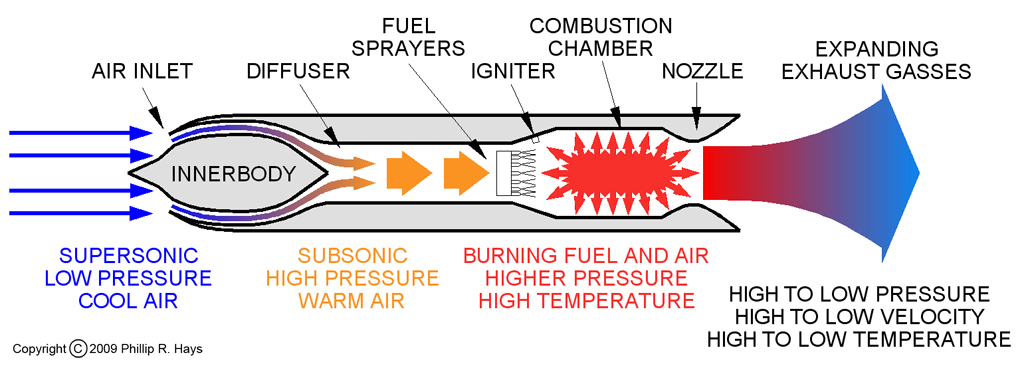
The ramjet works by increasing the overall speed of air passing through the engine. First, air entering the inlet is converted from low pressure, high speed supersonic flow to high pressure low speed subsonic flow. In effect, speed is converted to pressure high enough to support efficient combustion. Fuel is sprayed into the air, mixed, ignited by a pilot flame and burned in the combustion chamber. The pressure of the gasses is increased by the heat of combustion. Pressure from the burning air-fuel mixture pushes equally on the sides of the combustion chamber and against the airflow coming in the inlet. High pressures on internal parts of the engine push the missile forward. The exhaust nozzle allows excess pressure to escape, and the escaping gasses are accelerated to a higher velocity than the incoming air.
The engine converts the heat into thrust. The amount of thrust depends upon the mass and velocity of exhaust gasses leaving the nozzle at the rear of the engine. The mass of the gasses depends upon the volume of air ingested through the front end of the engine, and this is why ramjets do not work at low speeds. The engine must be moving at high subsonic speeds to ingest enough air to produce sufficient thrust to propel the engine. As speed increases greater amounts of air enter the engine, producing larger amounts of exhaust gasses and increased thrust. In effect, the faster it goes the faster it goes.
To achieve high efficiency the air inlet and exhaust nozzle designs must be coordinated to minimize pressure drop through the combustor.2 The air intake and exhaust nozzle are matched to produce the optimum pressure in the engine during flight. Exhaust gas momentum and pressure are in equilibrium with the pressures in the engine.
In the subsonic flow ramjet engine efficiency is sacrificed to achieve stable operating conditions. The maximum airflow rate is limited to slower than the speed of sound, while missile speed (air intake speed) increases beyond the speed of sound. Consequently, as speed increases the amount of air that flows through the engine is limited, restricting the total thrust that can be produced. But air resistance (drag) increases as the missile goes faster. At missile velocities of Mach 4 and higher the subsonic engine can no longer generate enough thrust to overcome drag and propel the missile faster. The Mach 4 Typhon ramjet missile24 that was developed as a successor to Talos operated at the limit of subsonic ramjet capabilities.
A number of supersonic flow ramjet designs have been proposed and tested to produce engines that can theoretically operate at hypersonic speeds as high as Mach 25.27, 49 However, no matter how fast the engine can go, as the missile or airplane moves faster and faster air friction heats the structure. As it gets hotter it gets weaker, and eventually it melts. The speed is limited by the materials the missile or aircraft is made of.
Ramjet Burner
The first problem the Bumblebee Program had to solve was the development of an efficient and reliable burner. Much of the development of a practical ramjet engine focused upon creating a burner that ignites reliably, can be reignited, and is immune to sudden variations in airflow and pressure inside the engine.
Quite a lot of research to solve these problems was going into ramjet design by many individuals, organizations and companies in the late 1940s and 1950s.2, 39 Much of the work was performed at NACA's Lewis and Langley research centers. Many combinations of fuel sprayers were tried with air deflectors around them in an attempt to protect the flame at the fuel sprayers, but this didn't improve reliability significantly.19, 28, 40 The numbers and arrangement of sprayers were varied, with little success. One experiment tried spraying water into the airflow to "smooth" burning.42 Others tried injecting reactive chemicals10 or oxygen41 into the air stream to keep burners operating under adverse conditions, but this just added to the complexity and weight of the engine. Some designs used multiple burners43 or a succession of increasingly larger burners9 in a single engine to attempt to use small burners to keep larger burners ignited. Alternative airflow paths were tried to improve combustion.8 Moveable exhaust nozzle plugs were tried as a means of controlling combustor pressure.31 Adding an afterburner to the ramjet was proposed, using the increased exhaust pressure from the afterburner fuel to regulate ramjet combustor pressure.33 Much of the early work was unsuccessful, but experiments did demonstrate that preheating the fuel improved ramjet combustion efficiency and operating range.34
The problems increased as the size of the ramjets grew. Small scale prototypes that worked fairly reliably were completely unsatisfactory when scaled up to sizes that might produce useful thrust. One approach was to bundle multiple small ramjets to provide increased thrust,36 but this required multiples of every part and much greater engine mass, effectively defeating the purpose.
A major problem that had to be solved was controlling the rate of combustion. It did little good to pump more fuel into the air stream if most of the fuel was blown out the end of the engine before it burned. To obtain maximum efficiency all of the fuel must burn inside the engine. Obvious as this is, achieving this goal was not easy.
Some amount of time passes between when the fuel-air mixture is ignited and when combustion is complete. Meanwhile, the burning gasses are passing through the engine at high subsonic velocities. Air passes through the 20 foot Talos ramjet from intake to exhaust in less than half a second, setting the time limit for complete fuel combustion.
Some fuels burn faster than others. High combustion speeds were desirable, but the fastest burning fuels were very dangerous to handle, often quite toxic, and expensive. These were all undesirable properties for something that was to be handled on board ships at sea. On the other hand, cheap and relatively safe fuels like aviation gasoline burned slowly. One solution to the problem was to initiate burning forward in the missile to allow more time for slow burning fuels to pass through to the exhaust nozzle. This meant that the entire length of the missile would be heated. That would require a substantially heavier heat resistant structure and would mean that the systems in the missile would need insulation to make them heat resistant. All of this increased missile weight and reduced range.
It was desirable to keep combustion at the rear of the missile, but this reduced burning time to less than a quarter of a second. Many fuels just didn't burn that fast. The problem was made worse by the hurricane-like conditions inside the missile. It was difficult to keep the air-fuel mixture burning, and flameout was common in the test vehicles.
Early ramjets typically sprayed fuel into the airstream at the front of the engine. Ignition was by means of a flare or artillery tracer aft of the fuel nozzles. This arrangement posed several problems. The flame could blow out the front of the engine if incoming air pressure dropped suddenly. Changing the amount of fuel introduced into the air stream controlled missile speed, and if the flow was reduced suddenly in order to prevent the missile from going too fast, the air fuel mixture could become too lean and the missile would flameout. Under other conditions the mixture would become too rich and burn unevenly, reducing the range of the missile.
As designs evolved ignition was moved to the rear of the engine, with a flame holder of some sort to prevent burning from moving forward.12 This typically was some type of "V" shaped channel or series of cones with the fuel introduced inside the apex. Gutter or grating-type21, 48 and rake-type15 flame holders were tried. Turbulence in the flame holder mixed the fuel and air and the mixture burned downstream of the flame holder. Cone-shaped perforated flame holders at the rear of the engine were also tried.6, 7, 32
Many different burner structures were tried but the early versions all had problems with dispersing the flame through the fuel-air mixture. They depended upon the flame spreading from the igniters through the passing fuel-air mixture, and this took time. Furthermore, if turbulence blew out the flame around an igniter unburned fuel would flow through the engine before the flame reignited and spread through the passing stream.
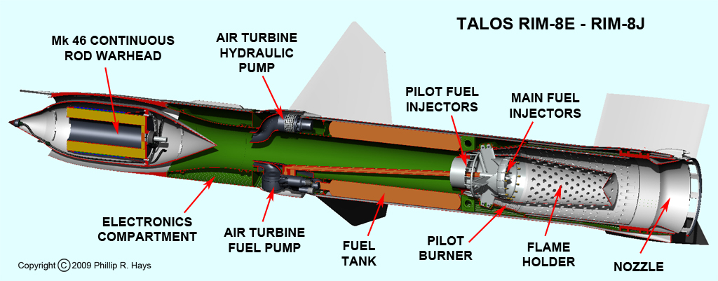
Eventually these problem were resolved by providing a constant flow pilot fuel metering system to keep the flame burning and a main fuel metering system to control airspeed.4, 5 For this to work the pilot flame needed its own burner to shield it from the main air flow. Also, the pilot air could not contain any of the fuel from the main fuel system, so it had to be diverted ahead of the main fuel sprayers. The obvious solution was to place the pilot burner ahead of the main burner and its fuel supply. The pilot flame blew into the main burner to keep it ignited, and allow it to restart if the main fuel supply was throttled back sharply.
The Talos fuel system incorporated a pressurized nitrogen reservoir. The pressurized nitrogen was released into an expandable bladder inside the fuel tank during the boost phase to provide a positive fuel pressure into the centrifugal fuel pump. A second valve opened before booster separation to allow fuel to flow into the pump. Pressurized air from inside the missile passed through an air turbine to drive the pump and then escaped to the outside air.
The fuel system had to meter fuel into the combustion chamber to control thrust (missile speed) and maintain stable combustion.23, 35, 47 A nearly constant and optimum fuel air ratio was required to produce maximum stability in the pilot burner. The fuel rate for the main combustor was varied from zero to maximum to control thrust. The prototype and First Tactical Talos (RIM-8A) fuel system controlled flow to maintain a constant speed. However, the temperature sensors used to control velocity were unreliable. In the Extended Range Talos (RIM-8C) and Unified Talos (RIM-8E) the fuel control system was modified to control speed as a function of altitude (pressure), so the missile flew slower at lower altitudes.22, 51
Between sea level and 70,000 feet the amount of air flowing through the engine changed by a factor of 17:1.52 The fuel system had to provide the correct fuel-air ratio at all altitudes, and had to do so within a few hundred milliseconds after booster separation. The fuel-air ratio had to be within the burning limits of the fuel (too lean or too rich and it didn't burn), and this had to be accomplished at up to 15g lateral and longitudinal acceleration and during missile roll. It had to work with low pressure in the combustion chamber at high altitudes, in the presence of vibrations and heating, and through sudden changes in air pressure when the booster separated or the missile maneuvered. And the mechanism had to be lightweight, reliable, have a long storage life and be inexpensive.
A pitot tube mounted on the front of the missile provided air pressure measurements for altitude and speed determination, and to determine engine airflow. This information was used to control fuel flow through the pilot and main fuel regulators. The pilot regulator had to adjust fuel flow rates over a 20:1 range, and the main regulator had to do the same over a 100:1 range.52 Fuel flow was regulated to provide the proper fuel-air mixture and fuel distribution during high-g maneuvers and variations in combustion chamber air pressure.
At high altitudes (60,000 feet) and high speeds (2000 ft per second) the combustion chamber had to operate with a relatively low inlet air temperature of 200°F and a pressure of 1/3 atmosphere. The early test engines did not work reliably for long periods at these conditions. This problem was also seen in turbojet engines that were being developed at the same time. There a solution was found by passing the fuel-air mixture through a perforated surface. As the mixture passed through the holes it swirled into vortexes downstream from the holes. The path it took around the spiraling vortexes was longer than the straight through distance. The longer flow path meant it took longer for the fuel to pass through the engine. Longer time meant slower burning fuels could be used efficiently.
Many different configurations were tried for these flame holders, all being variations on cylinders and cones. Some had cones that opened rearward and others were cones opening forward. Fuel was sprayed into the air flowing toward the flame holder and was ignited after it passed through the holes in the flame holder. These variations were tested in wind tunnels to find the most efficient configuration. Some were then flown in burner test vehicles to see how well they performed in flight.
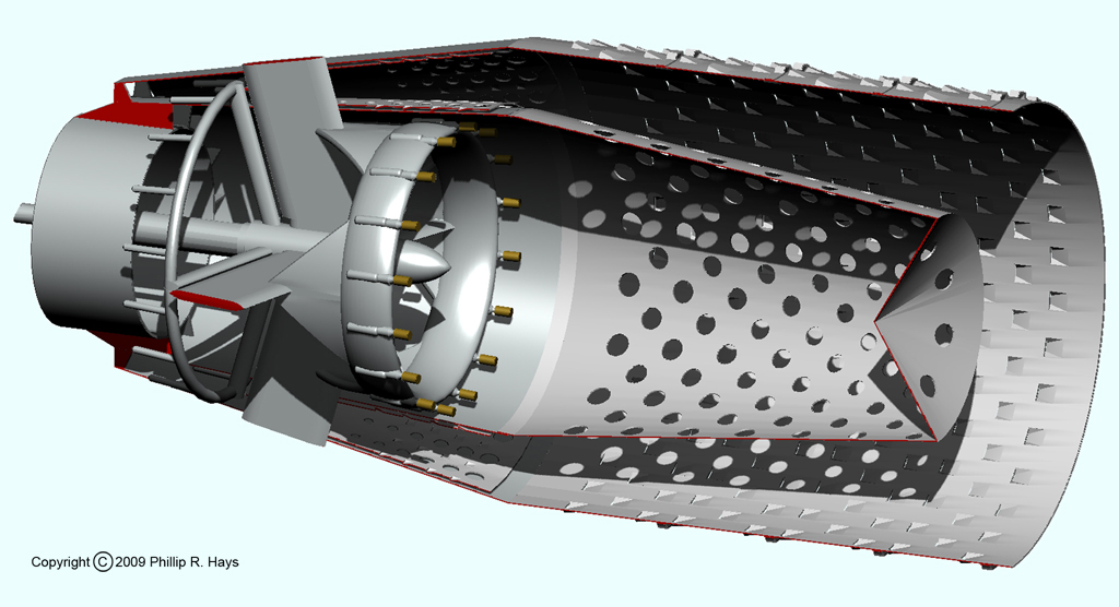
An elongated perforated flame holder can in the shape of a truncated cone with the wide end forward was tested successfully in 1950. It allowed efficient burning at low temperatures and pressures. The main fuel injectors were a circular array of nozzles that sprayed fuel into the air flowing into the cone. As the air-fuel mixture passed through holes in the conical flame holder it was both stirred and slowed by the vortex action as it entered the combustion chamber.
The pilot burner was located in a shell that surrounded the front end of the main flame holder. Air flowed around the pilot fuel injectors forward of the pilot burner and entered through holes in the shell. Inside the pilot burner a spark plug ignited the air-fuel mixture. The flame passed out of the pilot burner and flowed along the outer surface of the main burner flame holder, igniting the fuel-air mixture entering the combustion chamber. This configuration worked well at all altitudes.
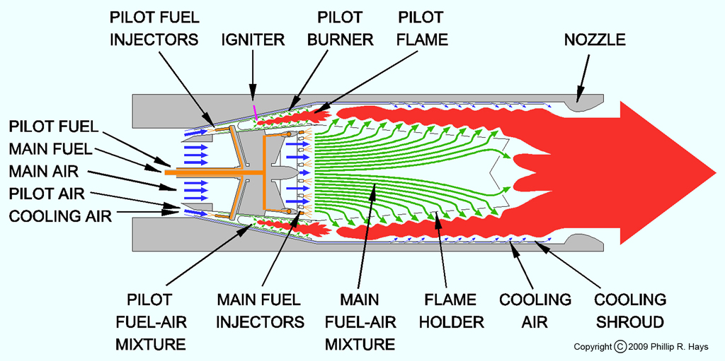
To protect the aft part of the missile body from heat the burner was surrounded with another perforated cooling shroud and part of the air flowing through the missile passed between this shroud and the inner wall of the combustion chamber. This cooler air picked up heat escaping the burner and then flowed into the combustion chamber through perforations in the shroud to mix with the combustion gasses.
Airflow was divided to direct 15% of incoming air into the pilot burners and 65% through the main combustor. The remaining 20% of incoming air was directed around the combustor to flow between the exterior wall of the combustion chamber and the cooling shroud.52 This design kept the hot gasses in the combustion chamber at the rear of the missile, and only this region had to be insulated or cooled. Combustion efficiency equaled or exceeded design goals, and the design was frozen in June 1951.
When higher speed missiles were developed it was possible to reduce exit nozzle diameter. This reduced air velocity in the engine, allowing longer time for fuel burning. This gave a major improvement in combustion efficiency, giving the missile a longer range. The combustion chamber was lengthened by 6 inches for the Extended Range Talos (RIM-8E) to improve high altitude cruise efficiency.
Even after a satisfactory design had been found, problems continued to arise. Fuel combustion produced 3500°F gasses and stainless steel melts at 2800°F or less. The solution to this problem was a zirconia coating on all burner surfaces to prevent oxidation and a new design to direct cooler air onto all metal surfaces. The pilot can regularly burned through at the junction with the cooling shroud. The solution was to increase the pilot fuel mixture to give too much fuel to burn in the dead zone where the fuel would absorb heat. Airflow wakes behind fuel system structures caused reduced airflow to some parts of the cooling shroud and decreased cooling of the engine wall. Small airfoils called turbulators were installed to restore the boundary layer. Another durability problem appeared with low angle launches of the higher speed Unified Talos (RIM-8E) where the combustion chamber wall burned through. The solution was increased thicknesses of the metal and zirconia coating, but this added extra weight.52
As development of the prototype Talos missile continued another serious problem appeared. During boost phase severe aerodynamic oscillations occurred in the compressed air inside the ramjet diffuser and combustion chamber. Tests were conducted at APL using a 1/7 scale model in a wind tunnel to simulate launching. Early in the boost phase the air in the diffuser and combustion chamber oscillated like an organ pipe at about 10 Hz. As speed increased the oscillations changed to about 50 Hz as the engine became a Hemholtz resonator. The oscillations pounded the internal components creating vibrations that damaged gyros and caused missile failure.56
Four modifications to prevent the oscillations were tested in wind tunnels. Vents were installed around the intake diffuser at the front of the missile to bleed off pressure during boost. The nose piece cone was extended during launch to deflect air around the intake opening. Flaps were added on the innerbody to partially close the intake opening. Openings were added at the rear of the combustion chamber, either in the airframe aft of the nozzle or through openings in the booster end cap. Experiments showed the openings at the rear of the missile vented enough air to prevent excess pressure buildup and oscillations during boost phase. They did not require a moving nosepiece or flaps and were the most easily implemented solution,56 and this modification appears on all subsequent Talos missiles.
Aerodynamic drag on the missile tended to hold the missile and booster together after the booster burned out and stopped producing thrust. When booster thrust decreased at the end of boost phase and no longer exceeded the aerodynamic drag of the missile the explosive bolt was fired on the clamp ring that held the missile and booster together to allow separation of the missile and booster. The ramjet could not be ignited until missile and booster separated enough to produce an opening at least as large as the missile exhaust nozzle opening. If the engine ignited while the booster was too close an explosion could occur which would damage or destroy the missile. The openings at the rear of the missile were designed to allow excess air to escape to prevent oscillations, but still maintain a pressure of about 45 psia in the combustor during boost.16 This pressure was sufficient to push the missile and booster apart after the clamp ring opened.
Igniter
The ramjet igniter posed several problems.16, 44 Pyrotechnic igniters were considered too hazardous for shipboard use so an electric spark igniter was chosen. Ignition was desired in a critical 40 millisecond window between boost and midflight phases. Ignition must be delayed at least 60 milliseconds after the clamp ring opened that held the missile and booster together to allow the booster to separate. Optimal ignition should occur less than 100 milliseconds after separation (however some missiles flew successfully that had delays as long as one second). The original spark unit fired 400 times per second, with 1.2 mjoules per spark, giving about 16 spark pulses during the 40 millisecond ignition window.16, 25
Atmospheric conditions inside the diffuser and combustion chamber during launch varied widely with ambient air temperature, pressure and humidity. Moisture condensation on the spark igniter was common because the metal parts were cooler than the air in the combustion chamber and due to the compression of the air. Salt in the water vapor was another problem. With time the igniter surfaces became passivated, and required a higher than normal voltage to initiate the spark. These problems occasionally caused ignition delays up to two seconds or complete ignition failure with the original spark igniter. Modifications to the original circuit failed to achieve the desired reliability.16
A new higher energy pulsed spark ignition system was developed that produced a faster rising spark to burn through the moisture and cause the spark igniter to fire.16, 17, 29, 54 The new igniter had to fit in the same volume as the original and could not require changes to the airframe for mounting and connections. It had to work for two seconds with the spark gap submerged in JP-5 fuel or in a saltwater fog.
The new igniter was designed to produce a 150 mjoule spark at a repetition rate of about 150 pulses per second (six pulses during the 40 millisecond ignition window). Pulse width was about 15 microseconds. The new system achieved first spark ignition in flight tests and gave a 30% increase in altitude for ignition.16 This system was a precursor to the electronic ignition systems in modern automobiles.
In later versions of the missile a backup pyrotechnic igniter was installed.16 It fired once during the critical ignition period, producing a ball of flame about a foot in diameter. It had superior performance over the spark system with low fuel/air mixtures. The spark system was still needed for reignition in case the engine flamed out.
Air Inlet
A ramjet needs a constant air supply for best operation. In practice this turned out to be hard to achieve. Air intake design was critical for the design of an operational missile. Numerous intake problems arose during Talos engine development, and some were especially difficult to solve.
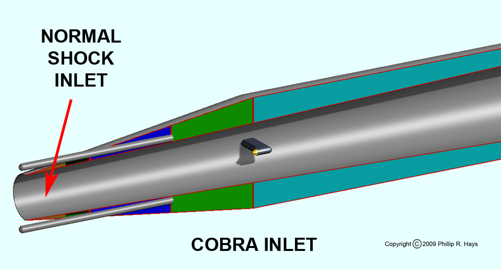
All ramjet designs from Cobra to XPM had "normal shock" air inlets (open tubes without a shock cone, also known as "pitot" inlets). The simple air inlet was not prone to oscillations when heat release from ignition or the presence of a booster blocking the nozzle reduced air flow in the engine. However, the normal shock inlet had a maximum operating speed of only Mach 1.2,3 and these engines could not maintain efficient combustion for long periods at high altitudes or high airspeed. A better air inlet design was needed.
Thrust is related to volume of airflow, so maximum flow is desirable. However, it is difficult to achieve reliable ignition with a high airflow. As the airflow increases in speed it becomes more difficult to keep the flame in the desired position in the burner - it tends to blow farther back in the burner and eventually blows out the nozzle, extinguishing the engine. High air speeds also reduce the time for fuel burning causing incomplete combustion in the engine. A method was sought to reduce the speed of the air passing through the engine without reducing the volume of air passing through.
A means was needed to stabilize airflow in the burner. During booster separation and engine ignition airflow inside the engine can change rapidly, and achieving reliable ramjet ignition can be difficult. Sudden changes in airflow can blow out the flame (too much air) or cause an over rich mixture (too little air) and reduced thrust. At high altitudes, where ramjets operate most efficiently, the low ambient air pressures amplified the problems.45 Changes in attack angle during sharp turns can starve the air intake, reducing airflow through the engine, causing the missile to decelerate or flameout.
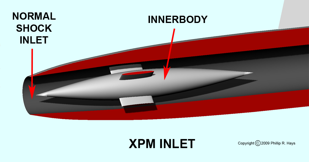
The solution to reduced flow rate and stable operating conditions was to place a compressor body in the intake duct. As air flows around the innerbody it is squeezed into the narrow opening around it. This reduces the speed of the entering air, converting high velocity to higher pressure. When the missile is moving at supersonic speeds the air in the engine is slowed to subsonic speeds. The same amount of air is available to produce high thrust, but it moves into the burner at subsonic speeds that allow better control of the fuel-air mixture and ignition. The picture shows the intake of the XPM. This design still suffered from the speed limitation of the normal shock inlet.
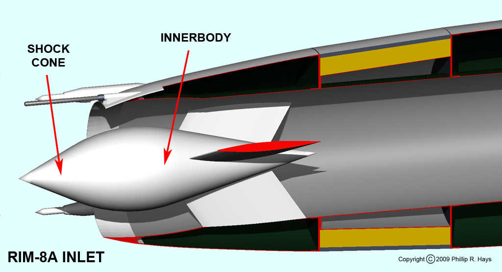
Wind tunnel tests showed higher speeds were possible if the compressor body was moved forward so the tip of the cone protruded ahead of the air inlet.54 This design was used in the prototype XSAM-N-6 and the First Tactical Talos RIM-8A. At supersonic speeds air velocity is first reduced by passing through conical shock waves from the tip of the compressor cone. Then the air is compressed near the intake lip in a normal shock wave (a shock wave perpendicular to the surfaces of the diffuser) to produce subsonic flow. The third stage is the subsonic diffusion behind the compressor body to give high pressure at the combustion chamber. This ramjet air inlet reduced air speed to velocities suitable for the combustion system and produced the highest practical pressure.
This type of ramjet can be operated in three modes that are related to where the normal intake shock wave is located. In the Critical mode the normal shock wave is located at the inlet opening, between the edge of the inlet and the surface of the innerbody. The supersonic shock wave flows back from the tip of the nose cone to meet the lip of the intake opening. This is theoretically the most efficient operating condition but it is difficult to maintain with changing altitude and during maneuvering.
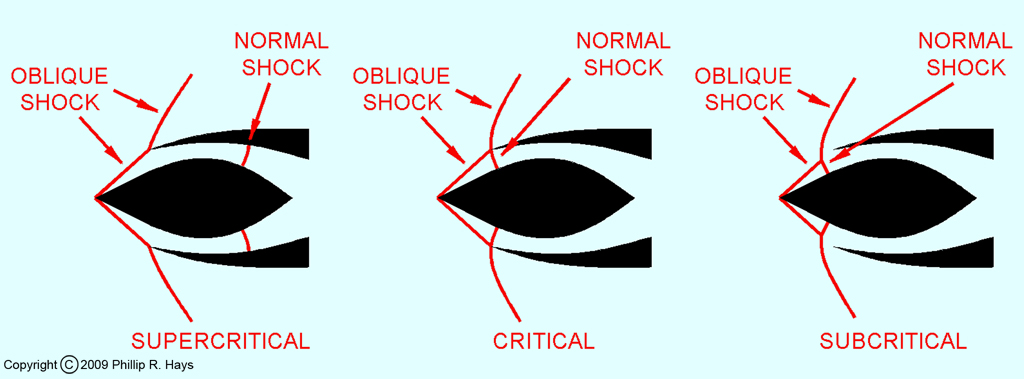
Supercritical operation occurs when the normal shock wave moves inside the inlet downstream from the cowl lip. This occurs with lean fuel-air mixtures and low internal pressures, and these conditions generate reduced thrust. This was not desirable.
In Subcritical mode the normal shock wave is allowed to move forward of the inlet opening and merge with the supersonic shock wave streaming back from the tip of the nose cone. The two shock waves merge at a distance from the nose cone surface. In this state some of the subsonic airflow behind the normal shock spills around the outside of the inlet. This occurs with rich fuel-air mixtures that create high internal pressures. This was the desired operating condition for the Talos ramjet engine.52
Much experimental effort went into determining the limits of acceptable subcritical operation18 and methods for achieving control.30 Three inlet designs were implemented before the final Unified Talos configuration was found. The initial inlet was a single cone design based upon data that showed better performance than a normal shock inlet. In 1953 the entire engine was redesigned. The inlet cone angle was increased to get higher supersonic compression. Inlet capture area increased from 205 to 235 square inches. Exit nozzle throat size was reduced from 70% to 60% of body area. These changes increased the thrust. The nuclear (W) versions had the same inlet cone with a reduced capture area to compensate for extra pressure loss around the larger innerbody.52
In late 1953 another inlet redesign was needed to allow higher operating speeds. The position of the normal shock front moves as missile speed changes. Also, as air pressure changes (with altitude) the shock front position moves. At lower altitudes where air pressure is high the missile speed must be reduced to balance the speed/pressure effect upon the shock front. As the missile increases altitude and air pressure drops speed must be increased to keep the shock front in the desired position. This is the reason Talos was launched to high altitudes and then guided to the target - it operated at highest speed and efficiency at high altitudes.
Flight tests of the new designs soon revealed a new and very serious problem. Talos engines were designed to operate at less than maximum air capture when combustion chamber pressure was high. This gave maximum engine thrust.52 However, operation in this subcritical regime led to instability in the diffuser-combustor system, allowing pressure oscillations that reduced thrust, caused vibrations, and could cause the flame to go out when operating near the limits of combustion stability. The vibrations were severe enough to damage gyros and cause missile failure.
When air encountered the point of the nose cone two phenomena occurred. First the air was pushed aside by the cone to form the supersonic shock cone. Air passing through this shock wave was decelerated to low supersonic speeds. In addition, air that came in contact with the cone was slowed further by friction with the surface of the cone. This created a boundary layer of slower moving air that flowed over the surface of the cone and into the engine. Consequently, where the incoming air encountered the normal shock wave there was a faster moving outer layer of air and the slower moving boundary layer.
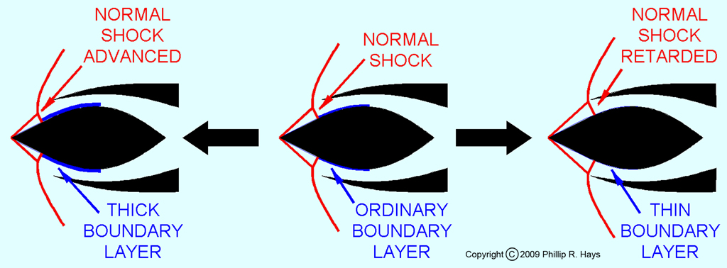
As long as pressure inside the engine was stable there were no problems. Under some conditions pressure inside the intake could increase suddenly causing a pressure wave to spread out forward of the inlet. This pushed the normal shock wave forward where it captured more air in the boundary layer. This generated a pressure wave that moved aft in the slower moving boundary layer. As a consequence the boundary layer thickened in the inlet opening, choking airflow into the engine. Air pushing into the inlet caused a secondary local pressure buildup at the front of the opening, pushing the normal shock wave further forward. The boundary layer became even thicker, choking the engine more. This process continued until the boundary layer completely filled the inlet and spilled around the cowl.49
When high speed airflow into the engine was choked off the internal pressure dropped. The higher pressure air blocking the inlet then flowed into the engine allowing the normal shock wave to move backwards. When this happened the slower moving boundary layer behind the normal shock wave became thinner. This thinner layer allowed more high velocity air to flow into the intake, causing internal pressure to rise again suddenly. In response the normal shock wave was pushed forward again, repeating the cycle even though the momentary transient condition that started the sequence was no longer occurring.
This oscillation is known as shock oscillation or compressor buzz.3, 11 The oscillation was the result of pressure changes resonating through the length of the engine from the inlet to the exit nozzle. This oscillation caused rapid pressure changes on internal surfaces that propagated as vibrations into the surrounding fuel, hydraulic and electronic systems.
The initiating condition, a sudden increase in pressure behind the normal shock front, could occur for a number of reasons. If the engine was suddenly throttled up the increased combustion caused a jump in internal pressure. When the angle of attack changed as the missile turned, the airflow into the engine dropped. When the missile assumed a straight course the internal pressure again rose suddenly.
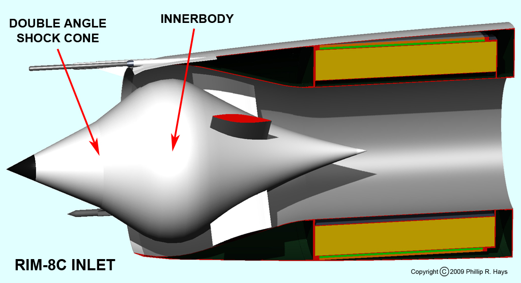
Changing the air inlet cone to have surfaces at two angles to the entering air stream solved the problem with supersonic shock wave induced oscillations. This created multiple shock waves that helped to reduce the disruption to air flow into the compressor. A double cone external compression surface with a forward cone half angle of 25° and a second half angle of 35° was chosen. This combination effectively prevented the normal shock wave from excursions far enough forward to allow shock oscillation to begin. Finer control of fuel flow rates using newer control systems that could detect the initial conditions that caused buzz helped avoid these conditions. The new intake design was incorporated into the RIM-8C Extended Range Talos and all subsequent versions. The higher compression angle and greater speed of the modified missile allowed a 360 square inch maximum inlet capture area. The exit nozzle throat was 65% of the body area.52
Fuel
While ramjet engine tests and design were proceeding many experiments were conducted to determine suitable fuels.1, 12, 15, 20, 21, 37, 53 Gaseous hydrogen was evaluated as a ramjet fuel.13, 14 For the desired missile speed and altitude a fuel should have the following properties:
1. Adequate specific impulse (the amount of propellant required to accelerate the missile a given amount).
2. Suitable rate of reaction with air to allow simple burner design and high combustion efficiency.
3. Fuel costs and the hazards of handling it should be reasonable.
How these are rated depends upon what the missile is supposed to do. For example, for long range the first two properties are important. Higher specific impulse produces more thrust per unit weight of propellant, allowing less propellant to be used. This lowers the mass of the missile, giving it still greater acceleration for a given thrust. If the fuel burns slowly some of it will be blown out of the tail pipe before it burns. High combustion efficiency means more of the fuel is burned and less escapes unburned in the exhaust, so less fuel is needed to generate the necessary thrust for the required amount of time.52
The Talos engine started self-sustained operation after booster separation and continued to accelerate as it climbed to operating altitude. The design goal was to fly at Mach 2.5 and 60,000 feet altitude. These criteria determined the temperature and pressure in the combustion chamber where fuel was injected, ignited and burned. Thrust was controlled by varying the amount of fuel.
Initially the reaction rate was emphasized to ensure the fuel burned while it was in the combustion chamber. Even though airflow was subsonic, air passed through the combustor in only a few thousandths of a second. If the fuel-air mixture took longer than this to burn, some of the fuel would be blown out the exhaust before it burned, reducing the efficiency of the engine. Carbon disulfide and propylene oxide were used in the early experiments because they burned more rapidly than ordinary hydrocarbon fuels (gasoline). As the design of injectors and combustors improved it became possible to use hydrocarbon fuels that had rapid enough burning, high specific impulse, and were also cheaper and easier to handle.
Another problem was getting the fuel to ignite under the dynamic airflow conditions during booster separation. Many fuels were tested and some were more easily ignited and burned faster, but had lower specific impulse. Boron hydrides had better properties 1 and 2 than hydrocarbons, but they were expensive and dangerous to work with. Improvements in pilot combustors and igniters allowed ordinary JP-5 jet engine fuel to be used in Talos.
The value of higher density fuels (more fuel per unit volume) was recognized and several alternate fuels were tested. Methylcyclopentadiene dimer (MCPD) was initially found to be a suitable substitute for JP-5. It has 12% higher heat release than JP-5 and worked well. However it polymerized into an unsuitable form when stored in the missile fuel tanks, producing a gum or varnish after a few months that prevented reliable operation of the fuel system.25
Eventually it was discovered that if this fuel was hydrogenated it became stable. This tetra-hydro methylcyclopentadiene dimer (T-H MCPD or RJ-4) fuel produced 143,000 BTU per gallon compared to 126,000 BTU per gallon for JP-5 (14% higher), and was used after 1966.25 RJ-4 does not polymerize to create a gum, produced less particulate residue than JP-5 and had no more long term effect on the fuel bladders than JP-5. It increased the maximum range by 20% to 30%53 and allowed a cruise altitude of 100,000 feet.25
The Unified Talos Ramjet Propulsion System
No major design changes were made to the ramjet after the Unified Talos (RIM-8E) missile was introduced. This design provided adequate, reliable propulsion for all Talos flight conditions. The double-cone inlet was designed for operation between Mach 2.0 and 2.5, with stable engine operation at lower speeds and maximum thrust. Fuel flow was regulated to keep flight speed between Mach 2.0 and 2.5 depending upon altitude. Either JP-5 or RJ-4 dimer fuel could be used with only a minor adjustment to the regulators. The missile carried enough fuel for a maximum range of 115 nautical miles (132 miles) with JP-5 and 130 nautical miles (150 miles) with dimer fuel.52
The final combustor design had conical sections to give concentric regions where pilot flame and the main air-fuel mixture came together to produce stable combustion. The fuel mixture passed through holes in the central flame holder cone that caused vortex wakes with a flow speed less than the speed at which the flame would spread through the fuel-air mixture. This produced the flame-holding action needed to get complete burning of the fuel within the combustion chamber. A spark plug in the pilot burner ignited the fuel and provided re-ignition during flight should the engine flame out. The nozzle at the rear of the combustion chamber reduced air speed in the combustor and matched pressure with the inlet.
1349 missiles using the Talos ramjet were flown during 25 years of testing and combat with a 96% engine success rate. In the Vandal program that followed the success rate was about 98%, using 20 year old propulsion systems.52
References
1. A Compilation Of Summaries From NACA Reports On Fuels Research, 1945-1952, J. T. DiPiazza, National Advisory Committee for Aeronautics, NACA RM 53D28, August 5, 1953.
2. Adaptation Of Combustion Principles To Aircraft Propulsion, Volume II - Combustion In Air-Breathing Jet Engines, Chapter XIV, Ram-Jet Performance, Fuels and Combustion Research Division, National Advisory Committee for Aeronautics, NACA RM E55G28, May 2, 1956, Page 243.
3. Aircraft Engine Design, Jack D. Mattingly, William H. Heiser and David T. Pratt, AIAA, 2002, page 448.
4. Air Fuel Ratio Control For Ram Jets, Walter D. Teague, Jr. and Pasquale A. De Padova, U. S. Patent No. 2736167, February 28, 1956.
5. Air-Fuel Ratio Control System For Ram-Jet Engines, Joel D. Peterson, U. S. Patent No. 2765619, October 9, 1956.
6. Altitude Investigation Of Can-Type Flame Holder In 20-Inch Diameter Ram-Jet Combustor, George R. Smolak and Carl B. Wentworth, National Advisory Committee for Aeronautics, NACA RM E54D08, June 3, 1954.
7. Altitude-Wind-Tunnel Investigation Of Various Can-Type Burners In Bumblebee 18-Inch Ram Jet, D. T. Dupree, T. J. Nussdorfer, and W. H. Sterbentz, National Advisory Committee for Aeronautics, NACA RM No. E8L20, March 16, 1949.
8. Analytical And Experimental Studies Of A Divided-Flow Ram-Jet Combustor, E. E. Dangle, Robert Friedman and A. J. Cervenka, National Advisory Committee for Aeronautics, NACA RM E53K04, January 11, 1954.
9. Apparatus For Igniting Fuels, James W. Mullen II, U. S. Patent No. 2867979, January 13, 1959.
10. Apparatus For Introducing A Reactive Chemical Into The Pilot Zone Of A Combustion Chamber, R. L. Duncan, David J. Miller, Frank R. Caldwell, Fillmer W. Ruegg and Ernest Fiock, U. S. Patent No. 3016704, January 16, 1962.
11. A Theory For Stability And Buzz Pulsation Amplitude In Ram Jets And An Experimental Investigation Including Scale Effects, Robert L Trimpi, National Advisory Committee for Aeronautics, NACA Report 1265, July 28, 1953, page 295.
12. Combustion-Chamber Performance With Four Fuels In Bumblebee 18-Inch Ram Jet Incorporating Various Rake- Or Gutter-Type Flame Holders, Ephraim M. Howard, Fred A. Wilcox and David T. Dupree, National Advisory Committee for Aeronautics, NACA RM No. E8I01a, December 2, 1948.
13. Combustion Of Gaseous Hydrogen At Low Pressures In A 35° Sector Of A 28-Inch Diameter Ramjet Combustor, William R. Kerslake, National Advisory Committee for Aeronautics, NACA RM E58A21a, April 22, 1958.
14. Combustor Performance Of A 16-Inch Ram Jet Using Gaseous Hydrogen as Fuel At Mach Number 3.0, Joseph F. Wasserbauer and Fred A. Wilcox, National Advisory Committee for Aeronautics, NACA RM E58K28a, January 18, 1957.
15. Comparison Of Two Fuels In Bumblebee 18-Inch Ram Jet Incorporating Rake-Type Flame Holder, Fred A. Wilcox and Ephrain M. Howard, National Advisory Committee for Aeronautics, NACA RM E8F11, August 18, 1948.
16. Development Of A Spark Ignition System For A Ramjet Missile, L. G. DeGrace, Journal of Spacecraft and Rockets, Vol. 5, No. 11, November 1968, page 1325.
17. Electrical Ignition Apparatus Using A High Voltage Breakdown and Condenser Followup Thorough The Ignition Gap, Louis H. Segall, U. S. Patent No. 3267329, August 16, 1966.
18. Experimental Investigation Of Diffuser Pressure-Ratio Control With Shock-Positioning Limit On 28-Inch Ram-Jet Engine, William R. Dunbar, Carl B. Wentworth and Robert J. Crowl, National Advisory Committee for Aeronautics, NACA RM E56F26, January 15, 1957.
19. Flame Holder Structure For Ram Jet Combustor, Herman I Wilson, U. S. Patent No. 2859588, November 11, 1958.
20. Flight Investigation Of Pentaborane Fuel In Rocket Boosted 9.75 Inch Diameter Ramjet Engine With Convergent-Divergent Exhaust Nozzle, John H. Disher, National Advisory Committee for Aeronautics, NACA RM E57F27, September 17, 1957.
21. Free-Jet Performance Of 16-Inch Ram-Jet Engine With Several Fuels, Fred A. Wilcox, National Advisory Committee for Aeronautics, NACA RM E50I06, October 31, 1950.
22. Fuel Control System For Ramjet Engine, William E. Worley and Richard B. Farrar, U. S. Patent No. 3092960, June 11, 1963.
23. Fuel Regulator, George D. Lewis, U. S. Patent No. 2861420, November 25, 1958.
24. Guided Missile, Alfred J. Bell, Ralph W. Blevins, Harvey J. Everett, William Garten and Everett J. Hardgrave, Jr., U. S. Patent No. 3403873, October 1, 1968.
25. High Density Fuel To Extend Range Of Ramjet Missile, Richard B. Farrar, Journal of Spacecraft and Rockets, Vol. 5, No. 11, 1968, page 1364.
26. The High Speed Frontier, Chapter 5, High Speed Cowlings, Air Inlets and Outlets, and Internal-Flow Systems, The Ramjet Investigation, John V. Becker, NASA SP-445.
27. History of Ramjet and Scramjet Propulsion Development for U. S. Navy Missiles, Paul J. Waltrup, Michael E. White, Frederick Zarlingo and Edward S. Gravlin, Johns Hopkins APL Technical Digest, Vol. 18, No. 2, 1997, page 234.
28. Igniter For Ramjet, John P. Longwell, U. S. Patent No. 2835109, May 20, 1958.
29. Ignition System Employing Saturable Core Reset By Relaxation Oscillator, James C. Morrison and Louis H. Seagall, U. S. Patent No. 3191093, June 22, 1965.
30. Investigation Of An On-Off Inlet Shock-Position Control On A 16-Inch Ram-Jet Engine, Fred A. Wilcox, Eugene Perchonok and Donald P. Hearth, National Advisory Committee for Aeronautics, NACA RM E54I21, November 29, 1954.
31. Investigation Of Effects Of Moveable Exhaust-Nozzle Plug On Operational Performance Of 20-Inch Ram Jet, William Sterbentz and Fred A. Wilcox, National Advisory Committee for Aeronautics, NACA RM E8D22, July 27, 1948.
32. Investigation Of Performance Of Bumblebee 18-Inch Ram Jet With A Can-Type Flame Holder, W. H. Sterbentz and T. J. Nussdorfer, National Advisory Committee for Aeronautics, NACA RM E8E21, August 24, 1948.
33. Investigation Of Ram-Jet Afterburning As A Means Of Varying Effective Exhaust Nozzle Area, Eugene Perchonok and Fred A. Wilcox, National Advisory Committee for Aeronautics, NACA RM E52H27, November 17, 1952.
34. Investigation Of The Performance Of A 20-Inch Ram Jet Using Preheated Fuel, Eugene Perchonok, Fred A. Wilcox and William H. Sterbentz, National Advisory Committee for Aeronautics, NACA RM E6I23, October 28, 1946.
35. Jet Engine Fuel Control Responsive To Inferentially Measured Combustion Gas Temperature, Richard C. German, Samuel E. Arnett, and Elmer G. Roberts, U. S. Patent No. 3019597, February 6, 1962.
36. Multi-Unit Ramjet, John G. Lee and Richard C. Mulready, U. S. Patent No. 2782593, February 26, 1957.
37. NACA Research On Slurry Fuels, M. L. Pinns, W. T. Olson, H. C. Barnett, and R. Breitwieser, National Advisory Committee for Aeronautics, NACA Report 1388, August 15, 1858, page 1273.
38. Note on the Cooling of Aircraft Engines with Special Reference to Radiators Enclosed in Ducts, F. W. Meredith, British ARC, R&M No. 1683, 1936.
39. Performance Of A 20-Inch Steady-Flow Ram Jet At High Altitudes And Ram-Pressure Ratios, Eugene Perchonok, William Sterbentz and Fred A. Wilcox, National Advisory Committee for Aeronautics, NACA RM E6L08, June 25, 1947.
40. Pilot Burner For Jet Engines, Whitney Collins, U. S. Patent No. 2780916, February 12, 1957.
41. Process And Apparatus For Operating Engines At High Altitudes, Herman L. Thwaites and Barrett B. Russell 3rd, U. S. Patent No. 2651173, September 8, 1953.
42. Ram Jet Burner With Aqueous Injection To Promote Smooth Burning, James W. Mullen II and John B. Fenn, U. S. Patent No. 2648196, August 11, 1953.
43. Ramjet Device, David H. Sloan, U. S. Patent No. 3049883, August 21, 1962.
44. Ramjet Ignition System, Donald G. Phillips, U. S. Patent No. 3055178, September 25, 1962.
45. Relation Of Turbojet And Ramjet Combustion Efficiency To Second-Order Reaction Kinetics And Fundamental Flame Speed, J. Howard Childs, Thaine W. Reynolds and Charles C. Graves, National Advisory Committee for Aeronautics, NACA Report 1334, August 5,1957, page 1249.
46. Rotor Blade Mounted Jet Engine, Stanley Hiller Jr. and Harold H. Sigler, U. S. Patent No. 2740282, April 3, 1956.
47. Simplified Theory For Dynamic Relation Of Ramjet Pressures And Fuel Flow, Herbert G. Hurrell, National Advisory Committee for Aeronautics, NACA RM E57I13, October 21, 1957.
48. Some Effects of Gutter Flame-Holder Dimensions On Combustion-Chamber Performance, Fred A. Wilcox, Eugene Perchonok and George Wishnek, National Advisory Committee for Aeronautics, NACA RM E8C22, July 30, 1948.
49. Supersonic Diffuser Instability, Charles Lee Dailey, Thesis in partial fulfillment of the requirements for the Degree of Doctor of Philosophy, California Institute of Technology, 1954.
50. Supersonic Ramjet Missile, Gordon L. Dugger and Frederick S. Billig, U. S. Patent No. 4291533, September 29, 1981.
51. The First Forty Years, Chapter 3, The Missile Age, Johns Hopkins University Applied Physics Laboratory, Schneidereith & Sons, Baltimore Md, 1983, page 19.
52. The Talos Propulsion System, William B. Shippen, Walter G. Berl, William Garten Jr., and Everett J. Hardgrave, Jr., Johns Hopkins APL Technical Digest Vol. 3, No. 2, 1982, page 127.
53. The Unified Talos, Frank A. Dean, Johns Hopkins APL Technical Digest Vol. 3, No. 2, 1982, page 123.
54. Theoretical and Experimental Analysis of Low-Drag Supersonic Inlets Having a Circular Cross Section and a Central Body at Mach Numbers of 3.30, 2.75 and 2.45, Antonio Ferri and Louis M. Nucci, National Advisory Committee for Aeronautics, NACA Report RM No. L8H13, November 10, 1948.
55. Theoretical Combustion Performance Of Several High-Energy Fuels For Ramjet Engines, Leonard K. Tower, Roland Breitwieser and Benson E. Gammon, National Advisory Committee for Aeronautics, NACA Report 1362, September 14, 1953, page 605.
56. Venting A Ramjet Missile To Prevent Buzz During Boost By Tandem Rocket, E. A. Bunt, Journal of Spacecraft and Rockets, Vol. 3, No. 7, 1966, page 1140.