
The Mk 37 Gun Director was the "eyes and ears" of the Gun Battery on the USS Oklahoma City CLG-5. It was mounted high in the superstructure on an armored barbette at the O5 level forward of the forward radar tower. The original CL-91 Cleveland class cruiser had two Mk 37 directors to control the six 5"/38 Gun Mounts and two Mk 34 Directors for the four 6"/47 Turrets. During the guided missile conversion in the 1950s the aft Mk 37 and Mk 34 Directors were removed. In 1963 the forward Mk 34 Director was removed to reduce topside weight and improve ship stability (the Oklahoma City was the only CLG to have the forward Mk 34 Director removed). After this conversion the Mk 37 Director controlled fire for the 6"/47 Turret and the 5"/38 Mount.
For direct fire against visible targets or targets being tracked by the Director's Mk 25 radar the Director supplied range, bearing and elevation to the gun control computers in the Double Purpose Battery Plot Room. For indirect fire against distant targets not directly visible the Director tracked reference points on shore to allow the Mk 48 Computer in the Surface Battery Plot Room to calculate the range and bearing from the ship to targets at known positions ashore.
The Director could be assigned targets from the Combat Information Center (CIC) or it could be aimed in the direction of targets by Target Designation Transmitters (TDT) in Forward Air Control directly in front of the Director Barbette on the O5 level. The Director crew could operate in Local Control and swing the Director around toward targets reported by lookouts, the Bridge crew, or targets spotted by the Director crew.
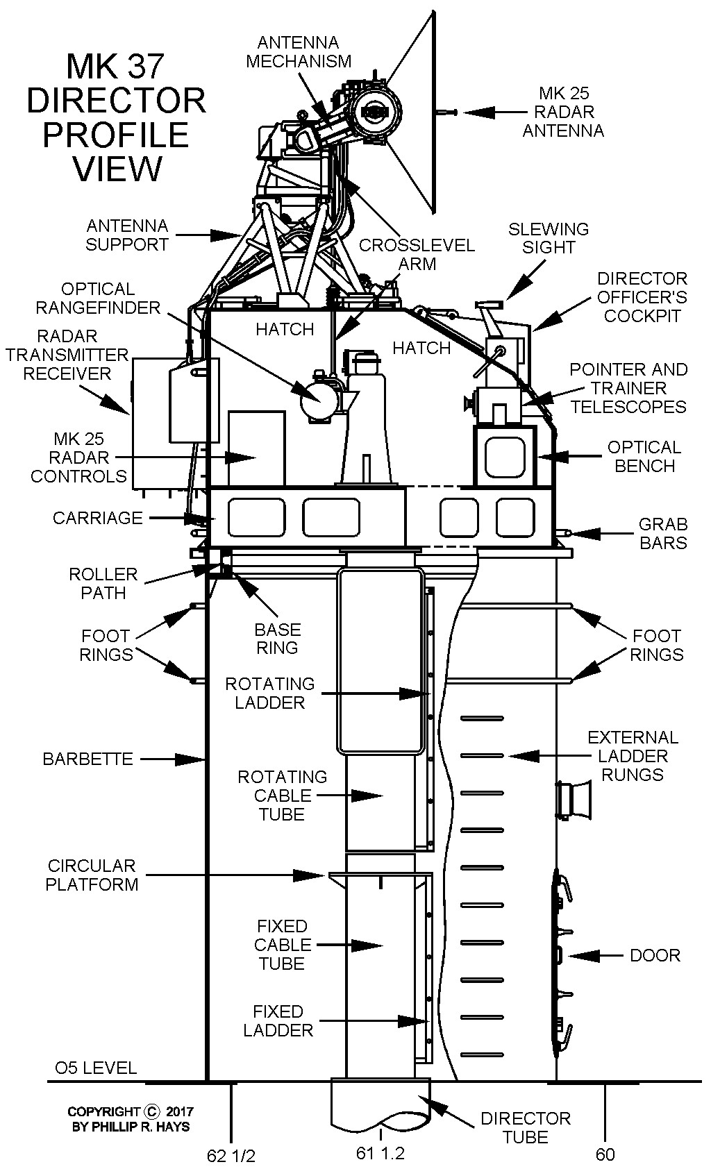
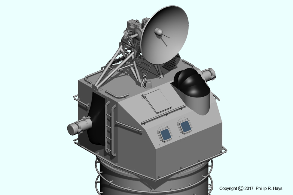
The Director was enclosed in a Shield made of 3/4 inch thick armor plate that rested on a Carriage at the bottom of the Director. The Carriage turned on roller bearings in the Roller Path on the Base Ring. The Base Ring was attached at the top of a 9 foot 4 1/2 inch diameter, 14 foot 3 inch high cylindrical Barbette of 3/4" thick specially treated steel armor plate. The mating surface of the Barbette was machined in place, after installation on the ship, to be parallel to the Turret and Mount roller paths to minimize alignment differences between the rotation axes that could affect aiming accuracy. A 22 inch diameter internal cable tube hung from the bottom of the Carriage to carry cables to the ship below. Beneath this was another 22 inch dimeter cable tube fixed to the O5 Level deck. Below this was a 31 1/2 inch diameter Director Tube of 3/4 inch thick steel that descended to the Third Deck to carry the cables down to Gun Plot. The Director could rotate ±375° to either side of the ship's center line - the limit to rotation was the amount of twist in the cables descending from the Director into the Director Tube.
Access into the Director was through a 21" x 57" armored air tight door on the front of the Barbette at the O5 level. A ladder climbed inside the Barbette to a platform on the lower central fixed cable tube. The upper rotating cable tube had a ladder that climbed to an opening in the Carriage. Climbing into the Director wasn't a problem if it was not rotating. But if it was the crewmen climbed the fixed ladder and then stepped onto the rotating upper rungs. This was especially interesting when the Director was turning and the ship was pitching and rolling. An alternate access route was to climb ladder rungs on the outside of the Barbette to two pipe foot rings that surrounded the Barbette. Then the crewmen held on to grab bars on the shell and walked around the rings to ladders on the sides of the Shell - this was especially dangerous if the Director was turning. After climbing the ladders and getting on top of the Director the crew could climb down through one of the hatches on the top.
The Director had two hatches at the top rear and one hatch at the center of the sloping front. In theory these allowed the Director crew to look out the top to observe the surroundings. In Vietnam the ship was in Condition II AAW or Condition II Shore Bombardment for days on end, with the Director continually manned with a one in three watch rotation. The Director was in the hot sun all day and became very warm inside, so the crew crawled out on top to escape the heat and catch some rays. The Director was the highest manned station on the ship and we had the best seats in the house. We also typically climbed the outside ladders to enter and exit the Director because the Barbette was uncomfortably hot inside.
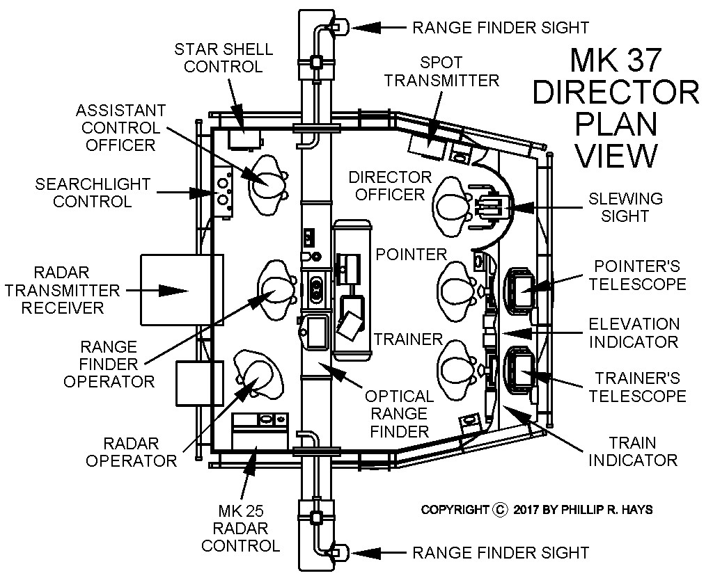
The Director had both optical and radar target tracking systems. A large Optical Rangefinder had two sights set 15 feet apart to produce stereoscopic images of the target that allowed optical determination of the distance to the target. The Pointer's Telescope and Trainer's Telescope were aligned to the Rangefinder's line of sight. The radar antenna on top of the director was also aligned with the optical line of sight, as was the Director Officer's Slewing sight. All rotated together with the Director around the vertical axis to stay pointed in the target direction. The Optical Rangefinder, Director Officer's Slewing Sight and the Radar Antenna rotated vertically to track the target in elevation. Prisms in the Pointer and Trainer's telescopes rotated so the view followed the target vertically in synchrony with the other elements. The Stable Element in Gun Plot generated cross level control signals for the crosslevel power drive to cause all of the optical and radar elements to tilt together to compensate for the ship's roll. A Crosslevel Arm connected the radar antenna to the Optical Rangefinder to keep them oriented horizontally and the Pointer and Trainer's telescopes were rotated inside their housings to keep them aligned with the other tracking elements. The crosslevel drive operated only though a ±17 1/2° roll angle and cut out at larger angles. It resumed operating when the roll angle was less than 17 1/2°.
The Director had a crew of six men during General Quarters. During Condition II watches only the Director Officer, Trainer, Pointer and Radar Operator were on watch in the Director. The Director Officer was in charge of the Director. He sat in a open "cockpit" that had a folding canvas cover that could be rolled back behind the officer's position. During direct fire missions he was in control of the entire gun battery. He communicated with CIC, the Bridge, Gun Plot and the Turret and Mount. He received target designations from a Target Designator in CIC or a TDT operator in Forward Air Control. When either operator selected a target an alarm sounded in the Director. The Director Officer pressed an "Accept Designation" button and the Director immediately swung around to face the target. If everything was aligned correctly the Director Officer, Trainer, Pointer and Radar Operator in the Director could see the target on their radar displays. If the target was not seen the Trainer and Pointer started a manual search of the target area. When the target was found they used foot switches to start automatic tracking. The Director Officer also served as a spotter to send corrections to the Computer in Gun Plot, and he also spotted corrections for illumination fire. The Director Officer's Slewing Sight could be rotated, like turning the handlebars of a bicycle, to send signals to the motors to cause the Director to rotate left and right at high speed to designate a target.
The Assistant Control Officer assisted the Director Officer and also was in charge of illumination fire. With Radar Control the Trainer, Pointer and Radar Operator used the Mk 25 Radar to track the bearing, elevation and range to the target. In Partial Radar Control the range was determined by the Radar Operator and the Trainer and Pointer used their optical telescopes and drive hand wheels to keep the Director aimed at the target in bearing and elevation. In Optical Control the Trainer and Pointer tracked the target's bearing and elevation and the Optical Rangefinder Operator determined the range to the target. The Rangefinder produced a split image with upper and lower images of the target. The Rangefinder Operator moved optical elements in the rangefinder to bring the images into alignment and determine the range to the target. The Radar Operator assisted by reading out the range from the Optical Rangefinder.
The Director could be moved in Manual, Local or Automatic Control. Automatic operation was the primary method of control. The Mk 25 Radar generated control signals to drive electric motors that rotated the Director and raised and lowered the tracking elements in elevation. The Mk 1A Computer in Gun Plot generated a predicted position for the target and sent signals to control the Director. The Mk 25 Radar then added correcting signals based upon the radar return signal to fine tune the motion to keep on track.
In Local Control the Trainer and Pointer used their telescopes to track the target and used their hand wheels to correct for errors in the Computer's predicted position. The wheels generated electrical correction signals to the Computer, and it drove the Director motors. In Manual Control the electric drive systems were turned off and the Trainer and Pointer's hand wheels were connected directly to the mechanical drive gears to move the Director. Manual Control was very slow.
The Director Officer, Pointer and Trainer had firing keys to fire the guns. The Trainer and Pointer had firing keys on their hand wheels. The Director Officer had a firing key on a cord.
References
1. NAVPERS 10175, Fire Control Technician 1 & C, Bureau of Naval Perconnel,1964.
2. BUPERS 10798-A, Naval Ordnance and Gunnery, Volume 2, Chapter 25, Linear-Rate Antiaircraft Fire Control Systems, Department of Ordnance and Gunnery United States Naval Academy, 1958.