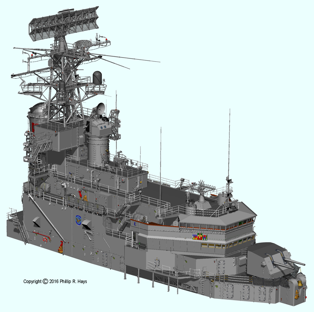
Forward Superstructure
The forward deck house had seven deck levels, from the main deck through the O4 level, with the O5 level radio room and O6 level electronics countermeasures shack below the forward tower. The ship underwent a continuing series of modifications and upgrades over the years, and there were many changes between the initial construction and the period (1971) that I am modeling. To discover these changes I had to examine hundreds of photos. Unfortunately, I do not have photos of some parts of the superstructure so a few small details may be missing. But for the most part this is an accurate depiction of the configuration of the ship in mid 1971.
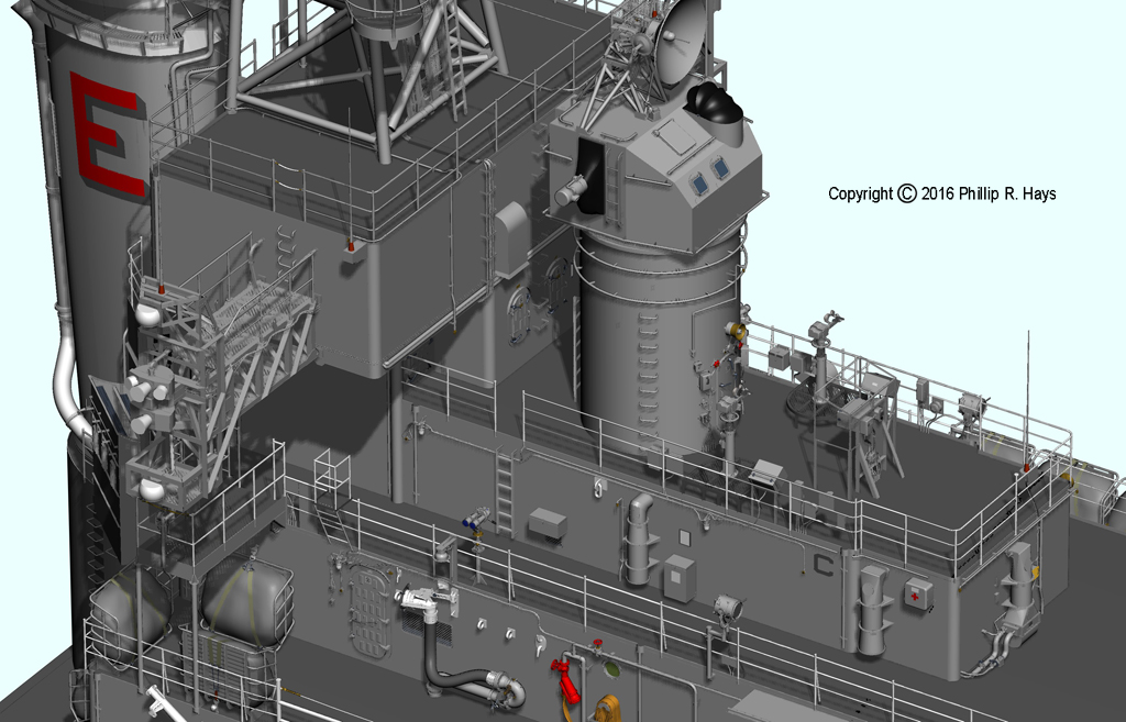
The superstructure supported the forward radar tower that carried the AN/SPS-43 air search radar, the AN/SPS-10 surface search radar, and an array of electric countermeasures antennas. The aft end of the deck house on the O4 level was the ship's signalling area with flag bags for the signal flags that were flown from the forward tower and search lights for visual communications with other ships. There were refueling stations port and starboard on the O3 level.
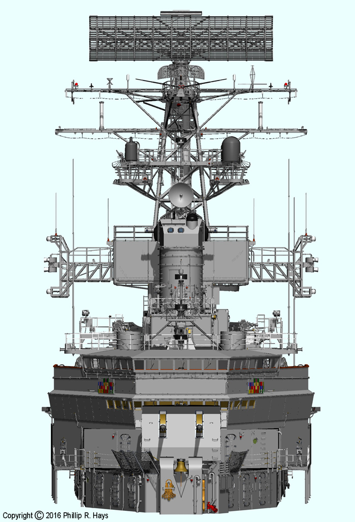
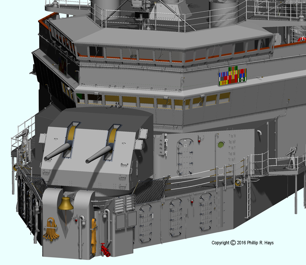
The ship was "conned" (controlled) by the Captain or the Officer of the Deck (OOD) from the navigation bridge at the forward part of the superstructure on the O3 level. This was where the action was. The watch was inside most of the time, under the metal awning over the bridge, but when maneuvering the OOD would step onto the open wings of the bridge to get a better view of the situation during a turn. During underway replenishment the OOD would conn the ship from the open bridge wing facing the replenishment ship. The ship could also be controlled from the open O4 level deck. Engine speed and rudder angle repeaters were on the light mast just forward of a pelorus (gyro compass repeater) with nearby a voice tube to the helmsman below. The ship's magnetic compass was also located on the O4 level just aft of the AN/SMQ-6 weather satellite antenna. When at sea the port and starboard lookout stations - the circular shields - were manned night and day.
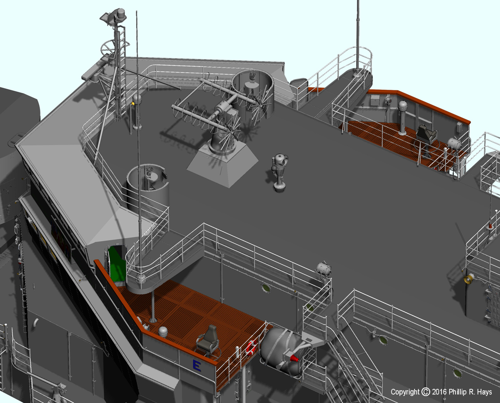
Forward Air Control was located on the O5 deck above the O4 level deckhouse, just forward of the Mk 37 director barbette. The station was a carryover from World War II antiaircraft duels with attacking planes and Kamikazes. It had two Target Designation Transmitters (TDTs) to be used to give bearing and elevation of approaching aircraft and communications and switching arrangements to assign targets to the Mk 37 director or the 5"/37 gun mount. By the 1970s it was an appendix of little use against supersonic aircraft and missiles. This was one of the least photographed parts of the ship. People took pictures from the O5 level, but rarely of the O5 Forward Air Control station. It was one of the most difficult parts to model.
The 5"/38 dual gun mount sat on the O1 level at the forward end of the superstructure. Below the mount were the 5" ammunition handling room, storage compartments and fan rooms. Behind the gun mount on the O1 level were some living spaces and the ship's communication center. Above the gun mount on the O2 level was the flag bridge and the Seventh Fleet War Room where the Navy's part of the Vietnam War was planned. Most of the forward superstructure housed offices and living quarters for the Admiral, Captain and Seventh Fleet staff.
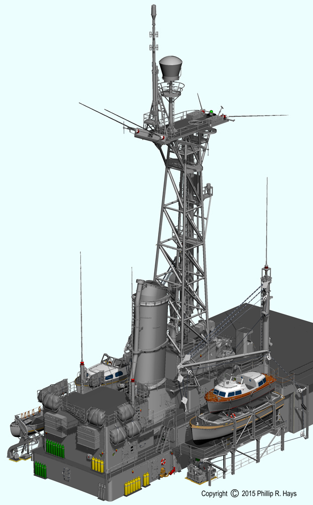
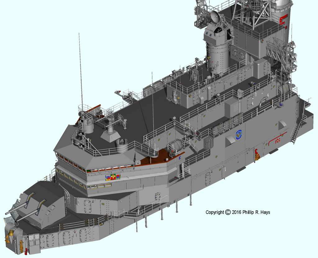
Midships Superstructure
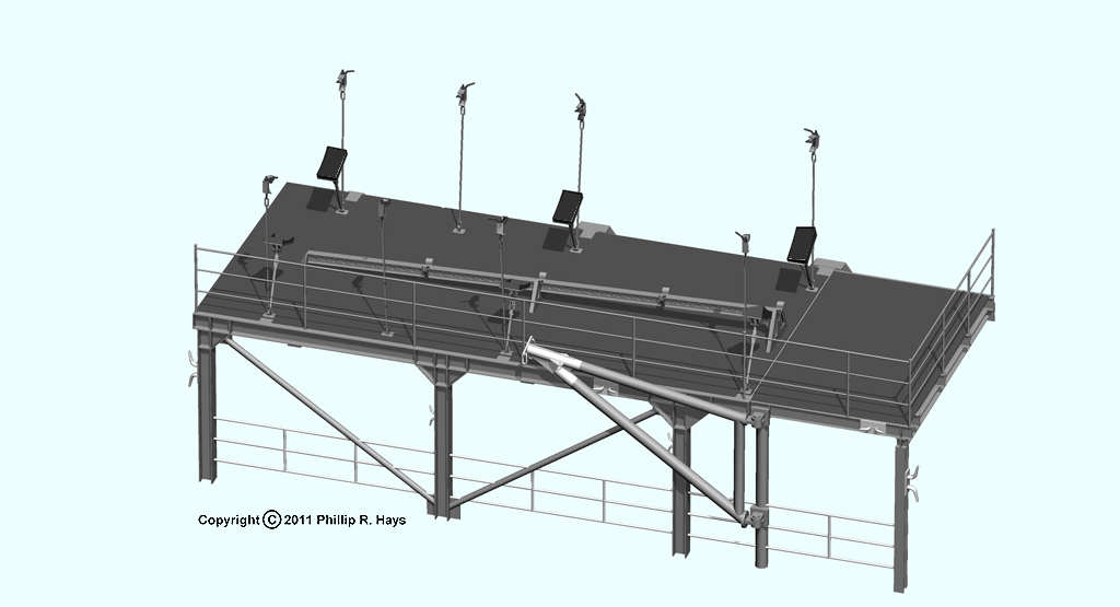
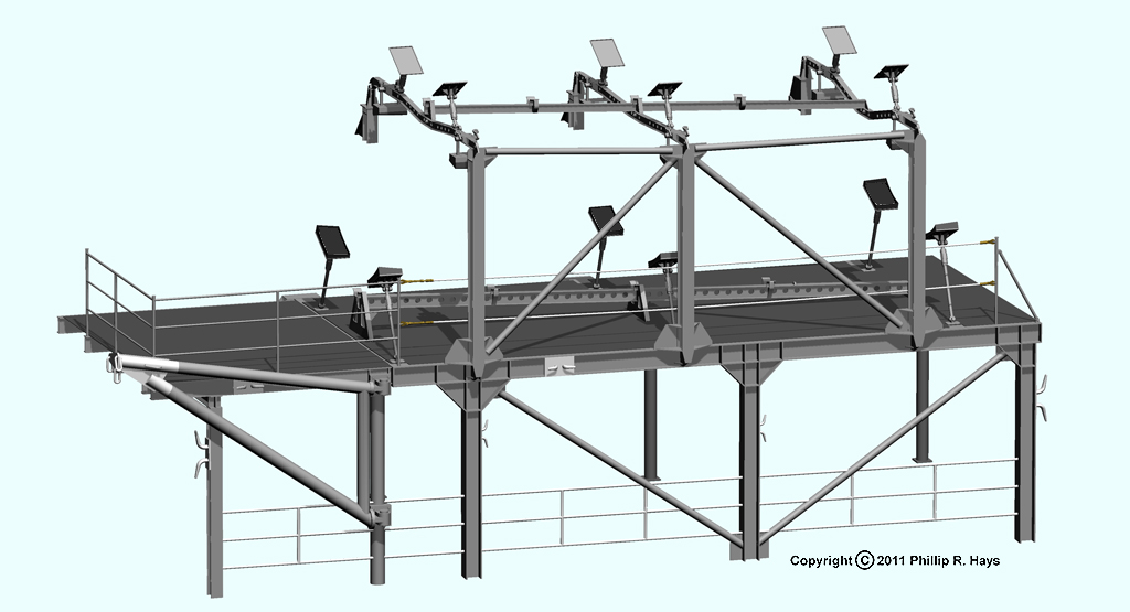
The midships deck house includes the boat decks, kingposts, boat booms and the winches used for boat movements and transfer of large objects from ship to shore. It supported the midships radar tower. These deck houses contained offices, workshops, radio rooms and living quarters. This part of the model is almost complete.
The least often photographed parts of the ship were in this area. I have almost no photos showing the areas below the boat decks and behind (looking inboard) the boat nests. To make modeling more interesting the deck houses beside and aft of the smoke pipe were extensively modified to add more compartments, and none of this is shown on the blueprints.
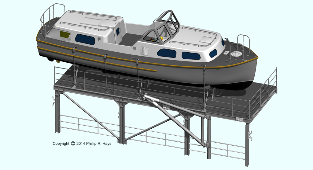
The boat decks were modeling projects in themselves. The boat supports and boat nests on the Oklahoma City in 1971 had been modified from the original blueprints. Enough of the original structure was still visible in photographs to allow most of the dimensions to be determined, but there was still a bit of "photoguestimation" necessary to piece together the entire structures. And the boats were each a modeling project.
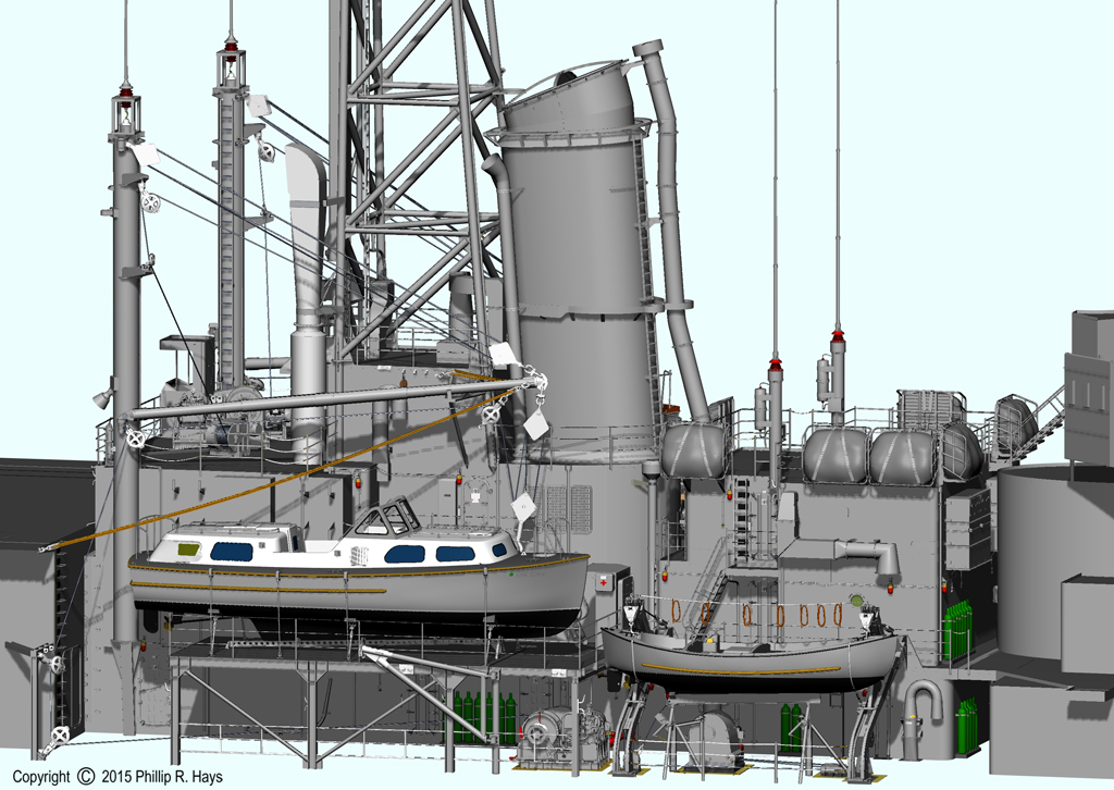
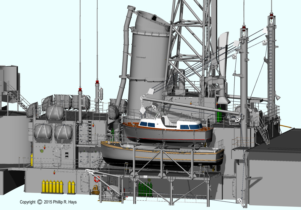
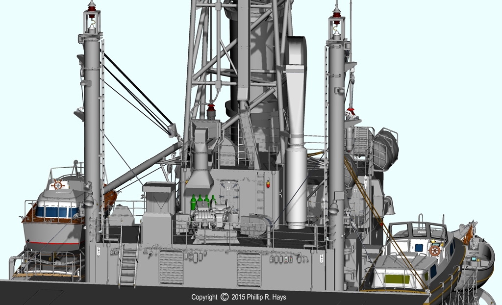
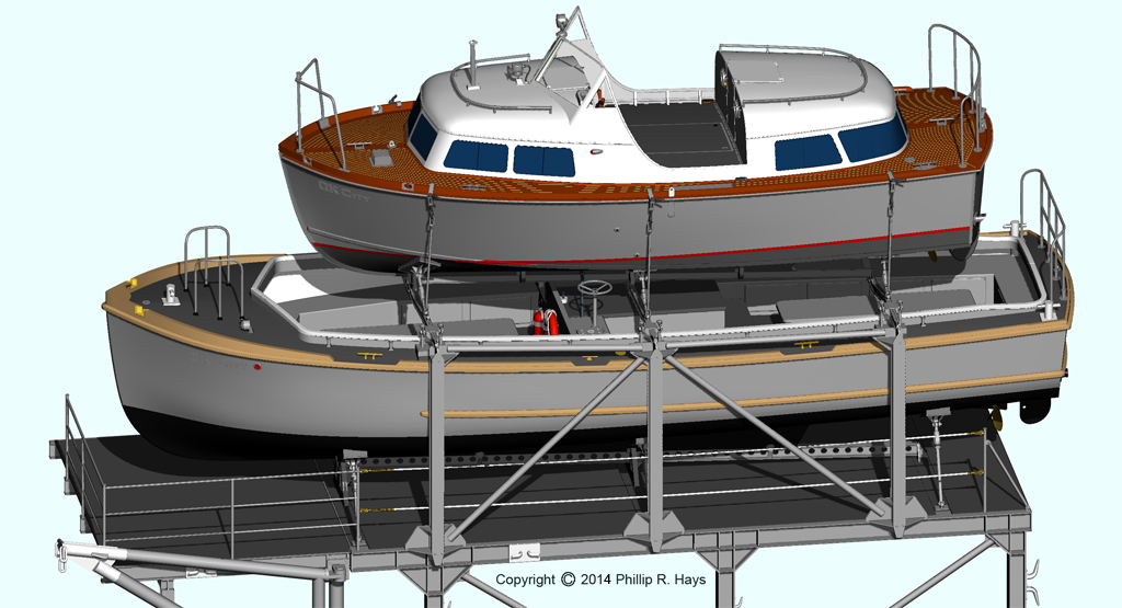
The starboard boat deck housed the ship's Mk 4 40 foot personnel boat. On the port side the Captain's gig Mk 6 28 foot personnel boat was nested above the Mk 2 40 foot utility boat.
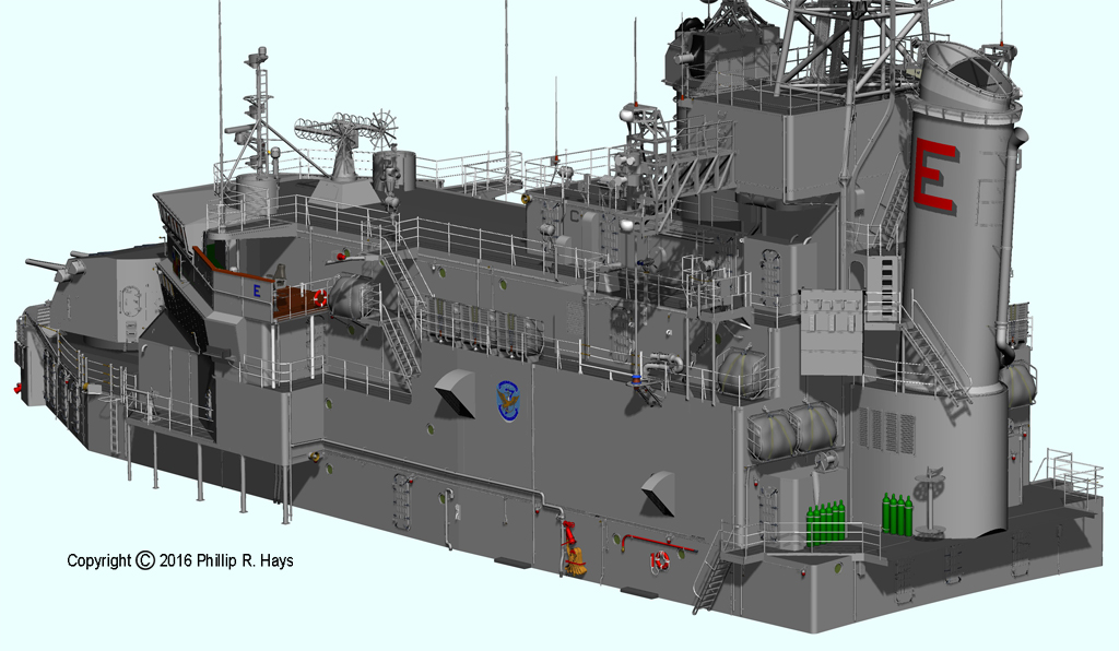
After Superstructure
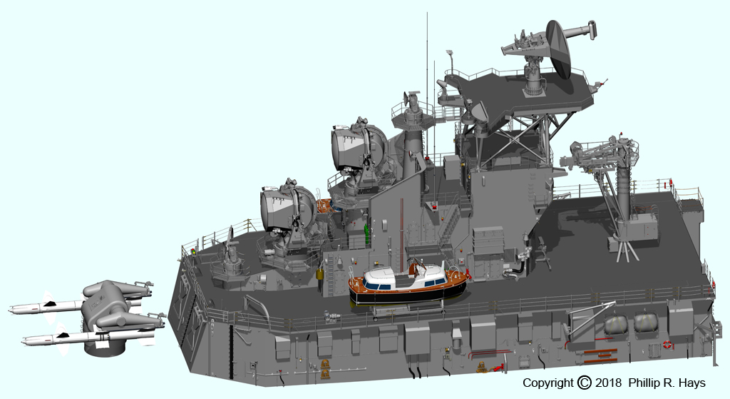
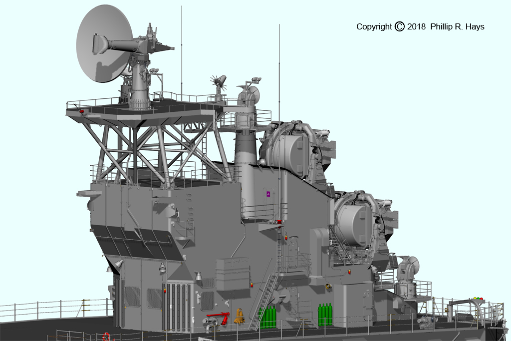
The after superstructure housed the Talos missile system. The lower part was the missile house where the Mk 7 Guided Missile Launching System was housed. It included the missile stowage magazine, ready service magazine, wing and fin area and missile test cells. Just aft of the missile house was the Mk 7 guided missile launcher where the Talos missiles were fired. On the forward end of the house (on the right in this image), above the missile stowage magazine, were the FAST crane and two strikedown hatches where missiles were lowered into or raised from the storage magazine during missile transfers. The open deck area here was the after transfer station for underway replenishment. Stores, ammunition and missiles were transferred via highline from and to replenishment ships at this location. The Admiral's barge and the 7th Fleet Staff boat were stowed on movable boat cradles positioned on the starboard and port outboard aft part of the missile house.
Above the missile house was the after deck house that supported the missile tracking and guidance radars. Inside the structure were the electronics spaces for the radars and Weapons Control where the missile system was operated. There were also fan rooms and gear lockers in the deck house. Refueling stations were located at the forward end of the deck house to port and starboard. Above the deck house was the after radar tower. This carried the AN/SPS-30 air search radar and additional antennas.
This part of the model is essentially complete, with all of the details like doors, deck drains, wiring and water wash down system piping..
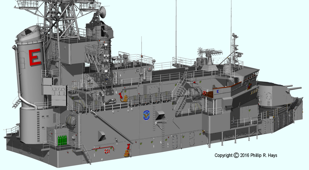
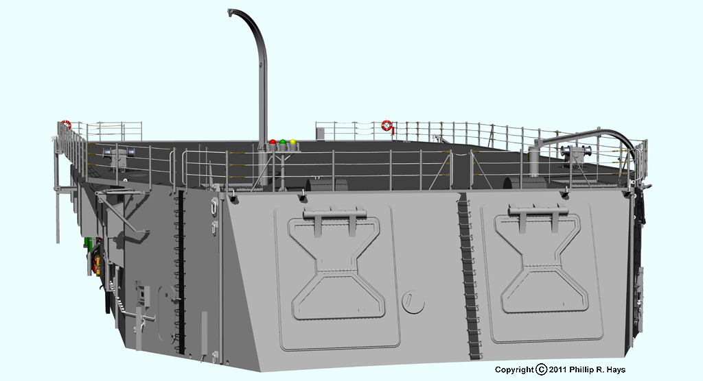
Missile House
The missile house is the simplest of the deck houses, but it still has a lot of details. The starboard warhead davit on the top of the missile house is shown in the stowed position and the port davit is raised for warhead transfer.
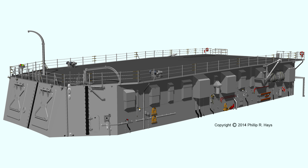
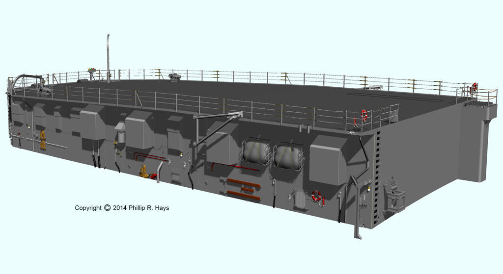
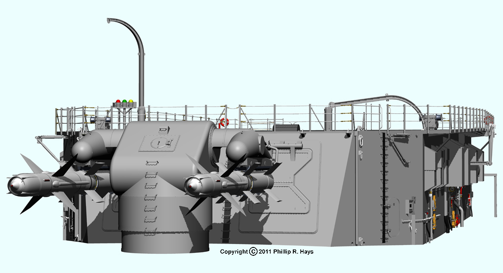
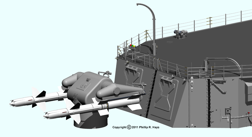
These images show the relationship of the Mk 7 Guided Missile Launching System inside the missile house to the Mk 7 Guided Missile Launcher. The blast doors on the face of the missile house opened and a rail on the top door mated with the rail on the launcher. Missiles were pushed out of the missile house onto the launcher and then the blast doors closed. The launcher could be trained in bearing across the stern of the ship through a large arc from side to side to launch the missile. However, it was desirable to launch off the side of the ship to minimize the amount of burned paint on the missile house.
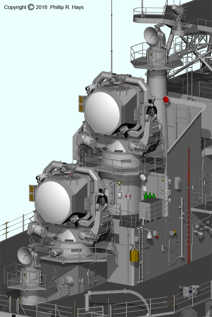
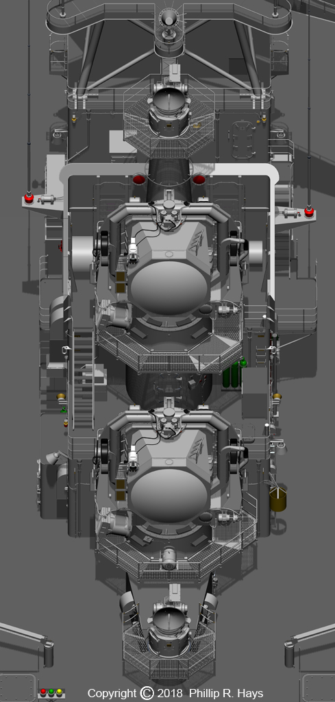
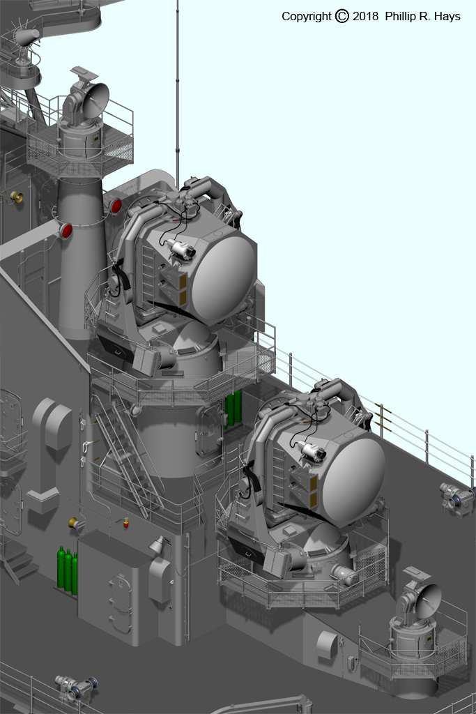
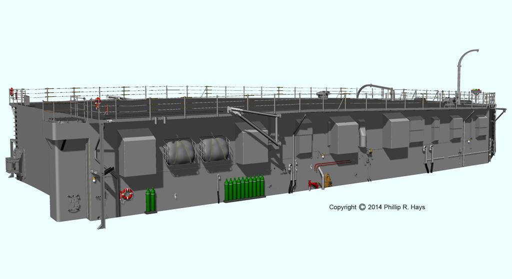
After Deckhouse
The after deckhouse sat atop the missile house. It housed the Mk 77 Guided Missile Fire Control System, including two AN/SPG-49 missile tracking radars and two AN/SPW-2 missile guidance radars and associated equipment, and Weapons Control where the missile system was operated. The aft radar tower rested on top of the deck house. It carried the large AN/SPS-30 3D air search radar, AS-791/UPA-43 IFF antenna, AS-979A/UKR telemetry antenna and a few other antennas.
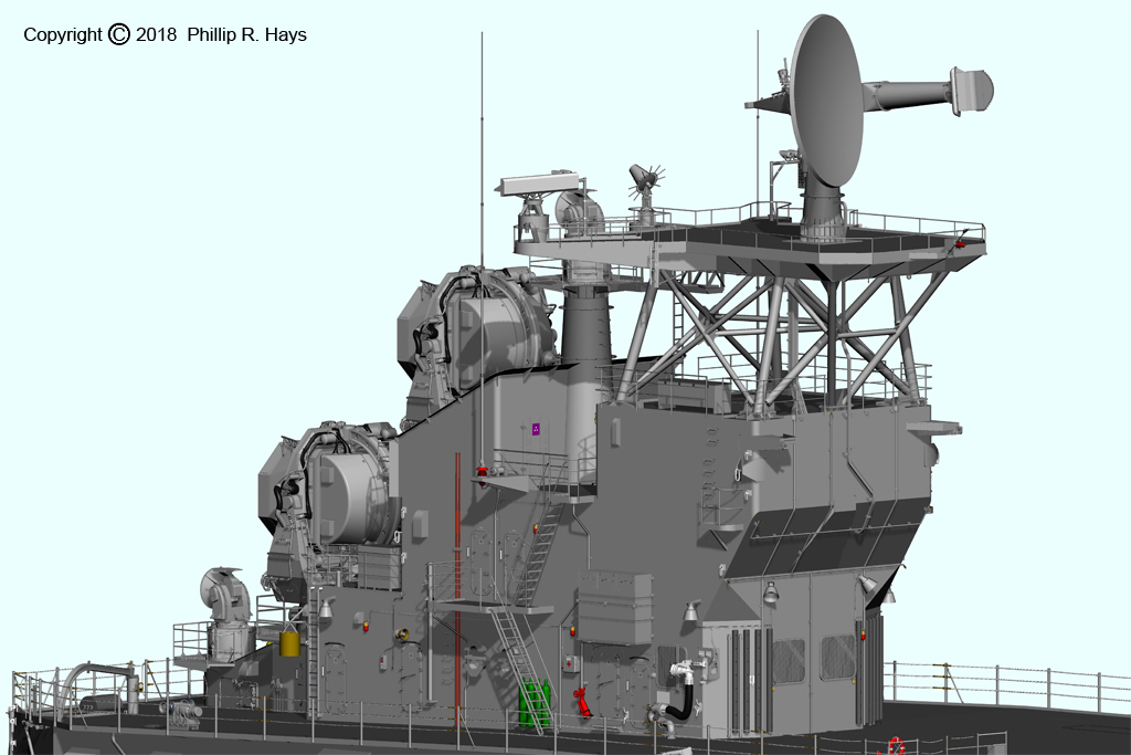

The black rubber hoses fastened to the front of the deck house served as bumpers for when missile transfer carts were being handled in rough seas. At the forward starboard side was a refueling station rigged with a receptacle for for quick connections. Port forward was another refueling station, but without the quick connection equipment.