FAST Crane
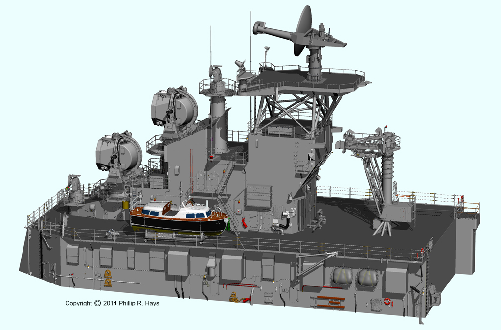
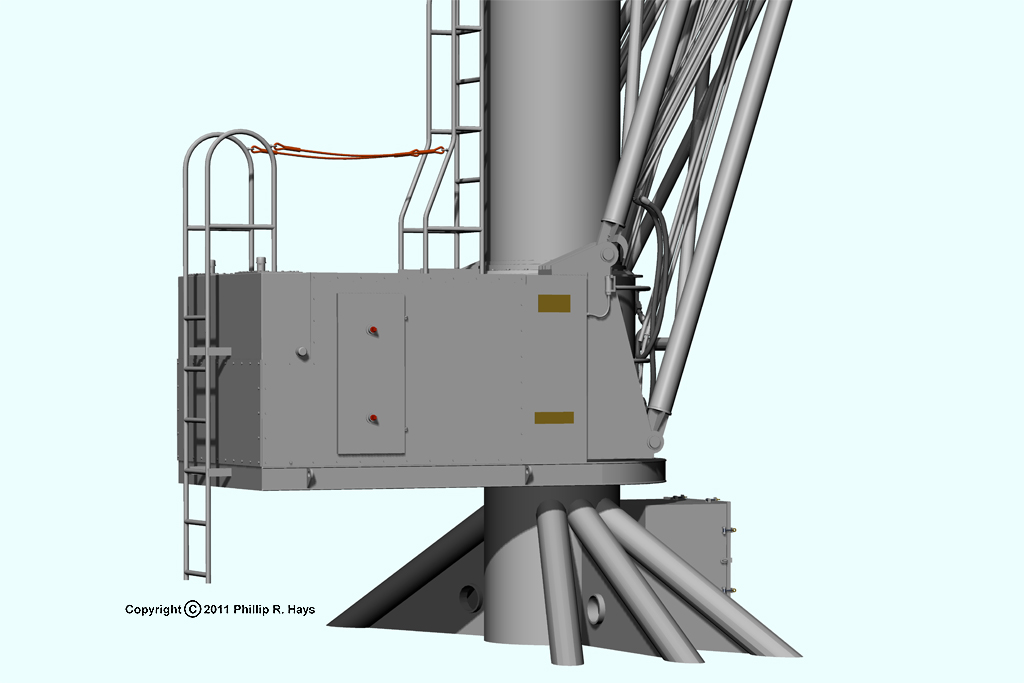
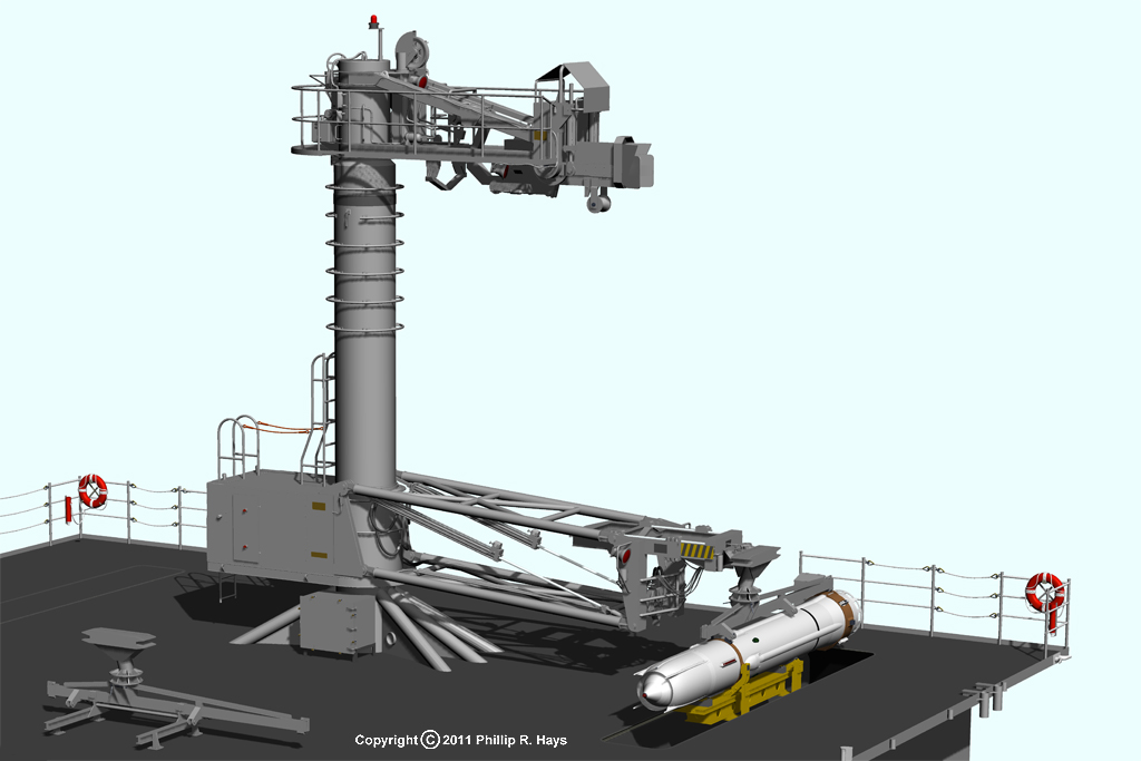
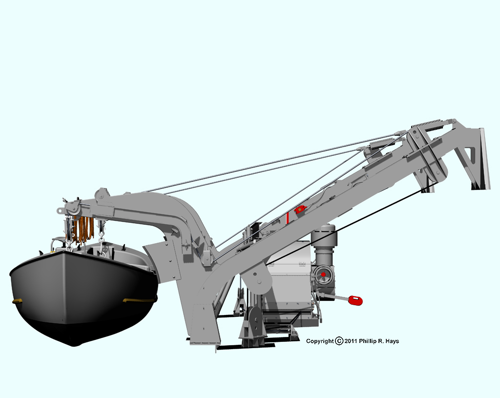
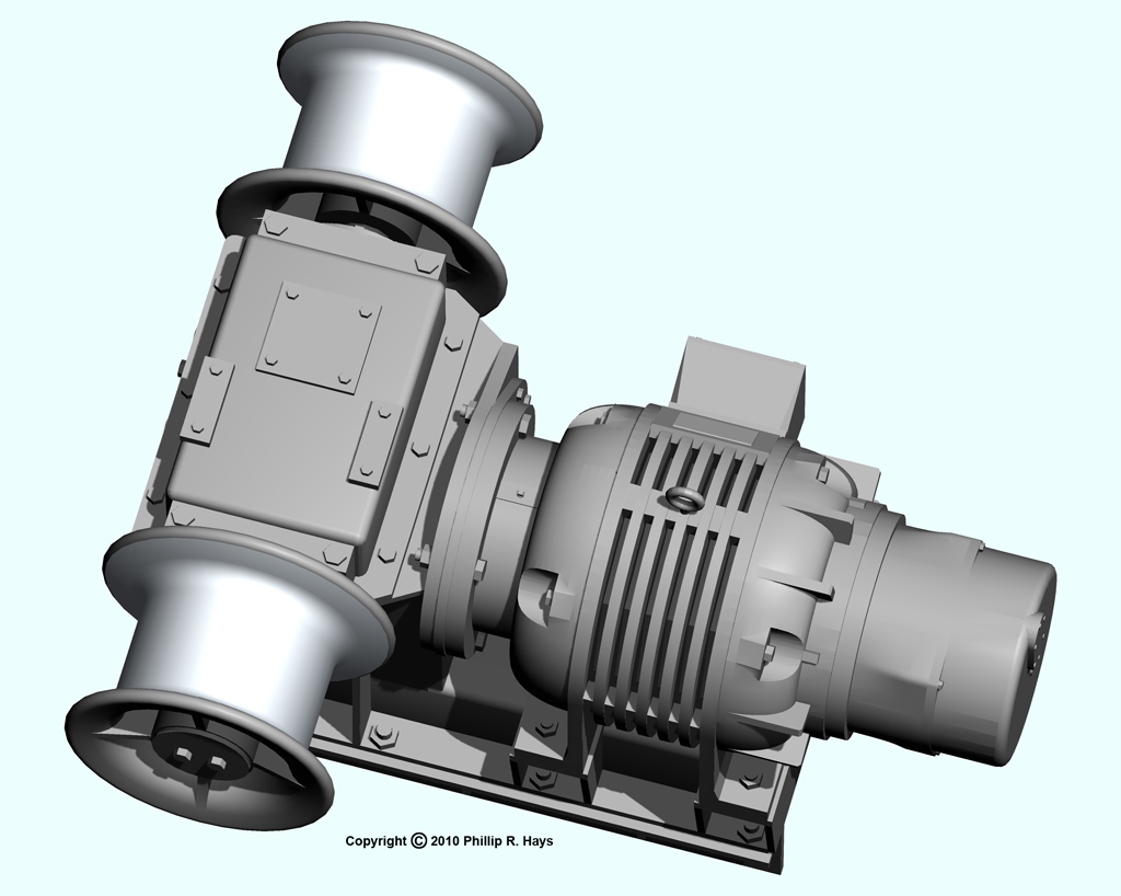
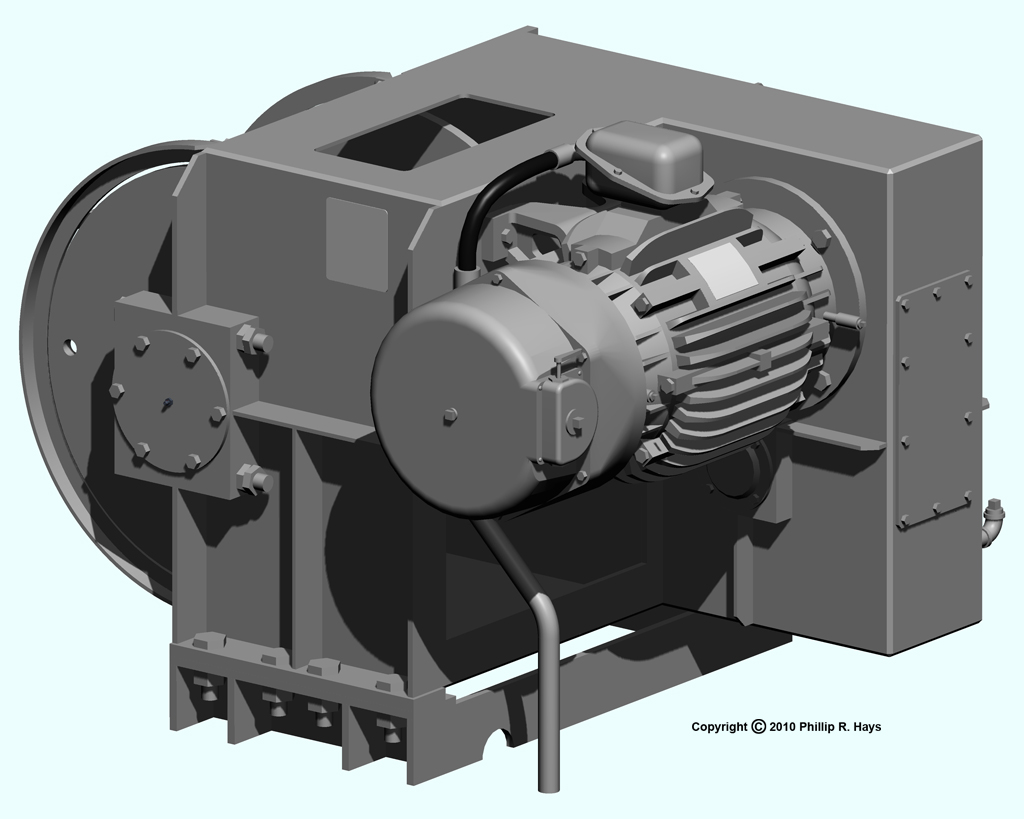
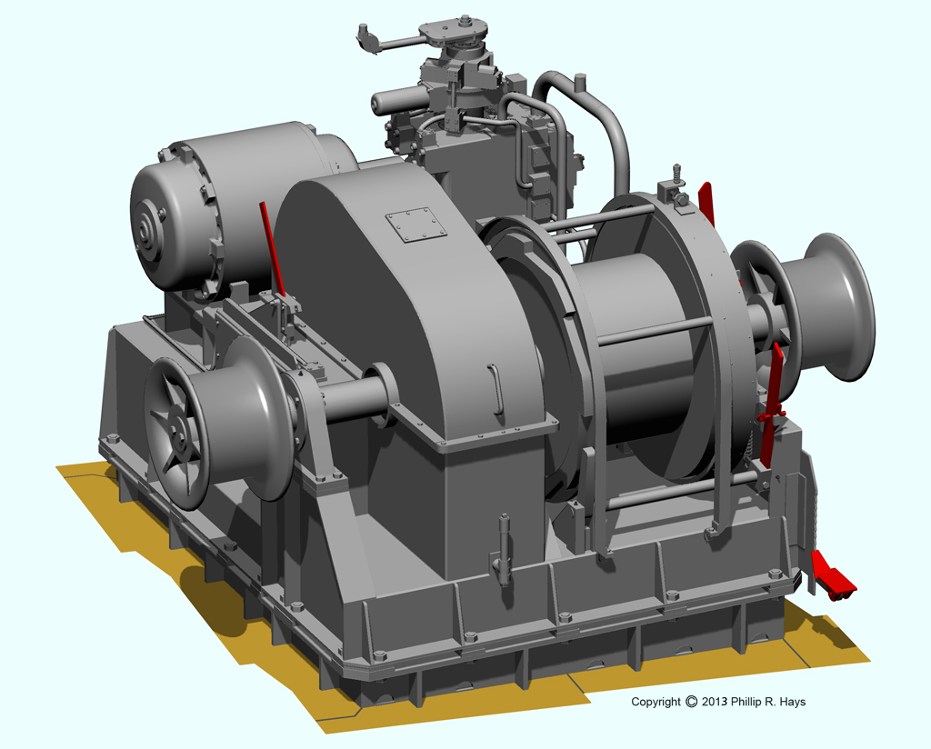
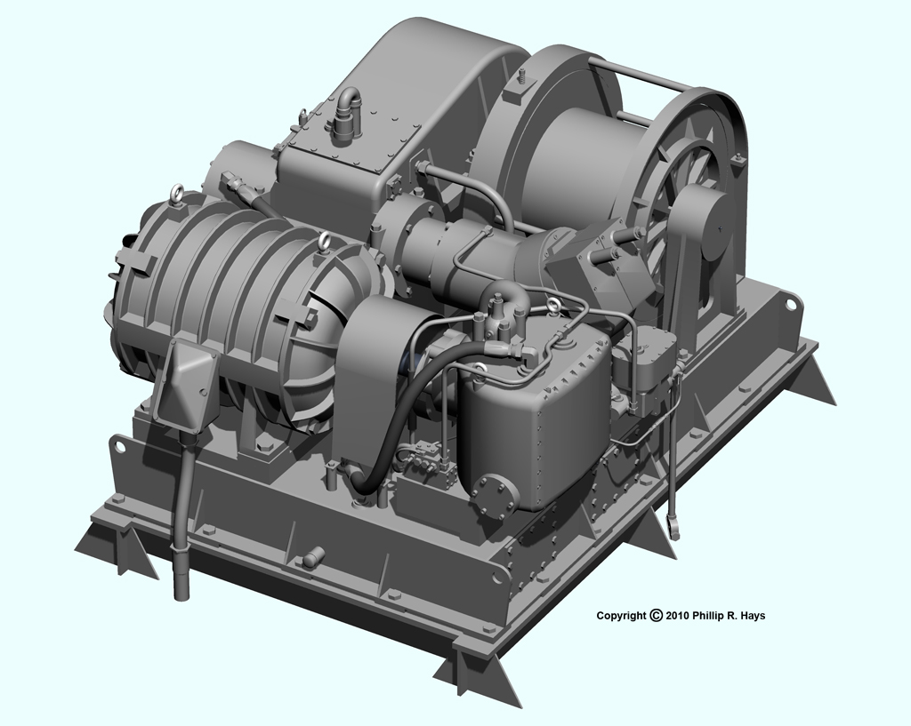
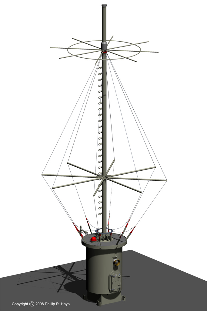
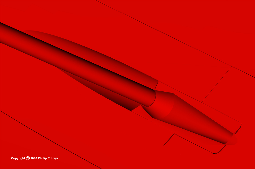
The FAST crane (Fleet Automated Shuttle Transfer) was one of those great ideas that really wasn't so great after all. It's function was to automate missile transfers between a supply ship and the Oklahoma City. The FAST system was installed in 1963 as an improvement to underway rearmament. It did not work reliably and was removed from the ship in mid 1971. After the mechanism was removed the kingpost remained and was used for ordinary highline transfers of missiles and boosters. This image shows the location of the FAST crane on top of the missile house.
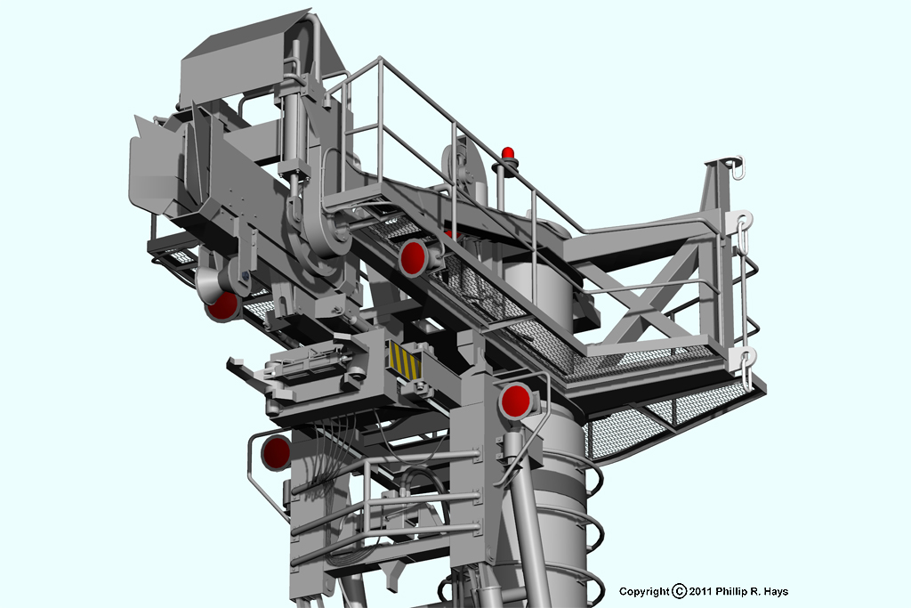
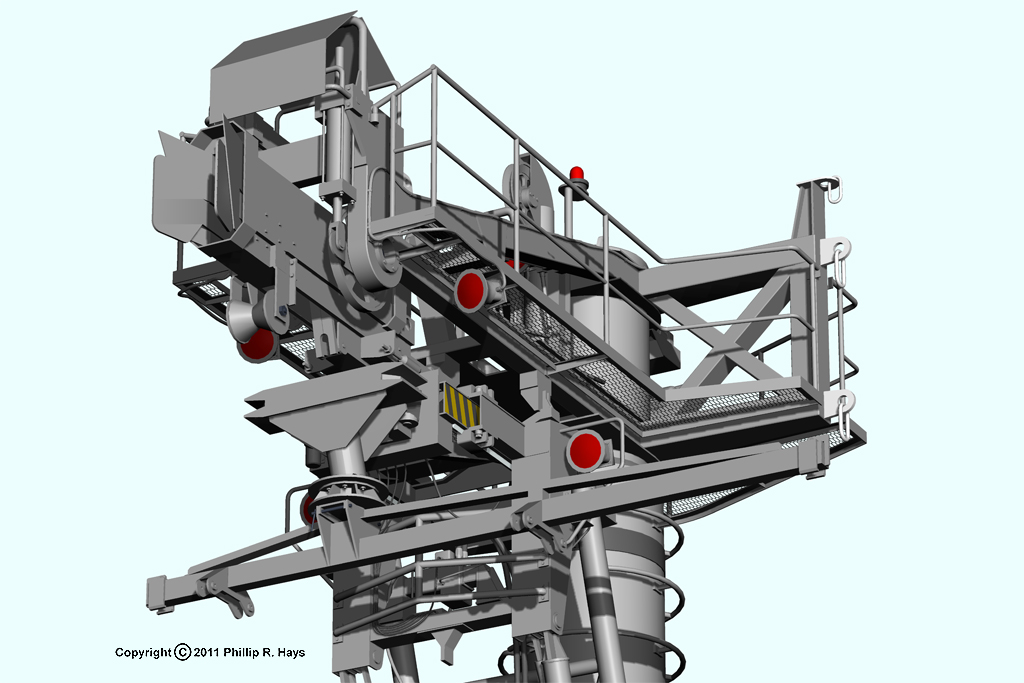
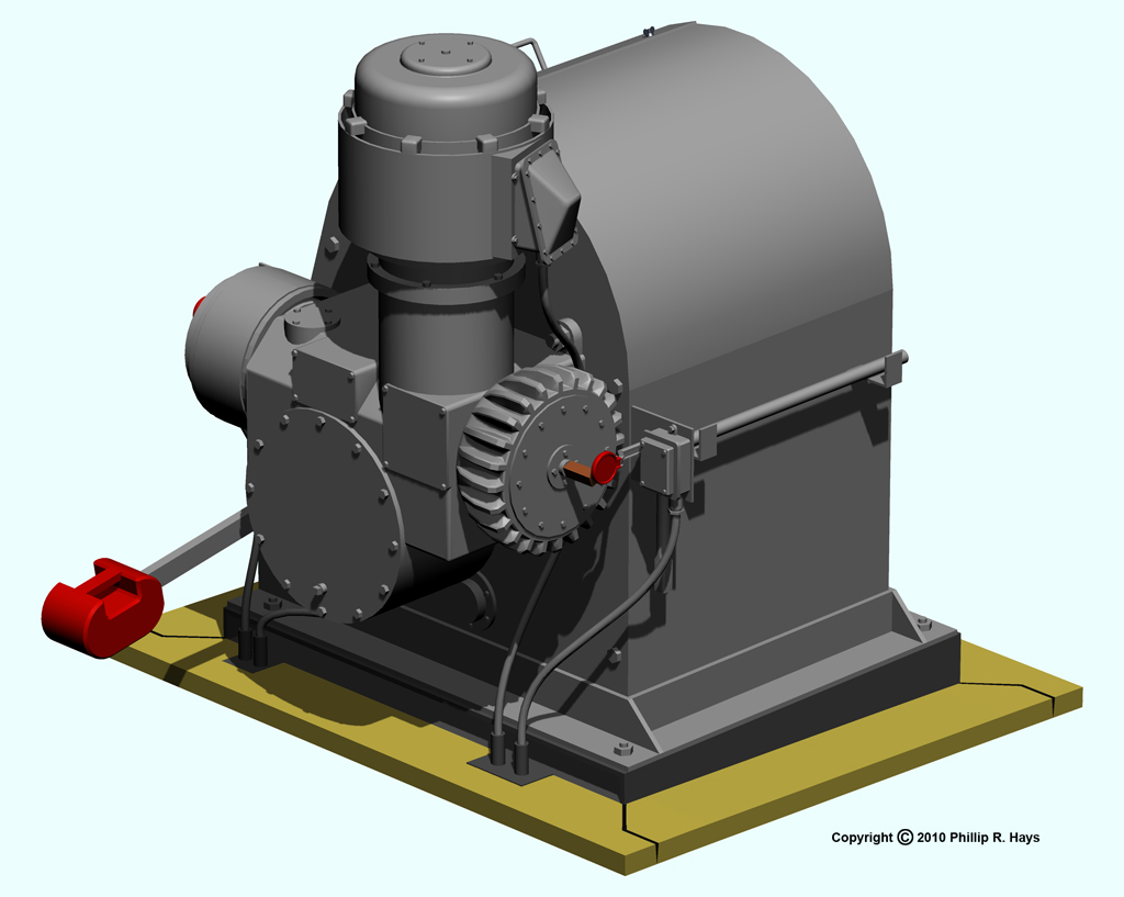
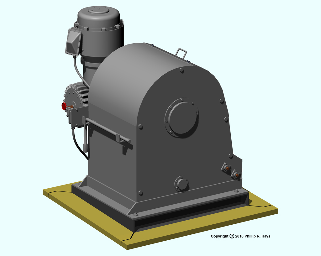
This was one of the most difficult parts of the ship to model. It was a plumber's nightmare with lots of pipes, cables and bits and pieces of machinery fastened all over. To make the project harder, I have found no dimensioned drawings or blueprints to work from. I have quite a few photographs but most are fuzzy shots taken from a distance. Only three were detailed close ups, and they didn't show the entire structure. Consequently, the dimensions are only approximate and quite a bit of the details are guesswork created from blurry images.
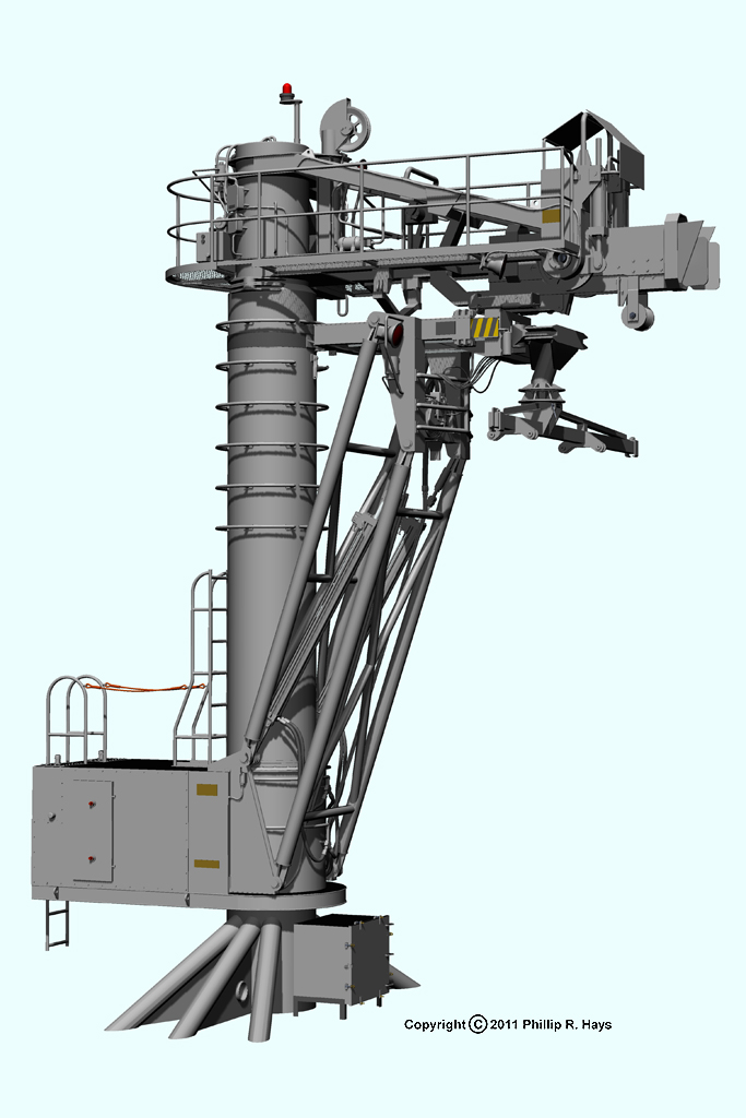
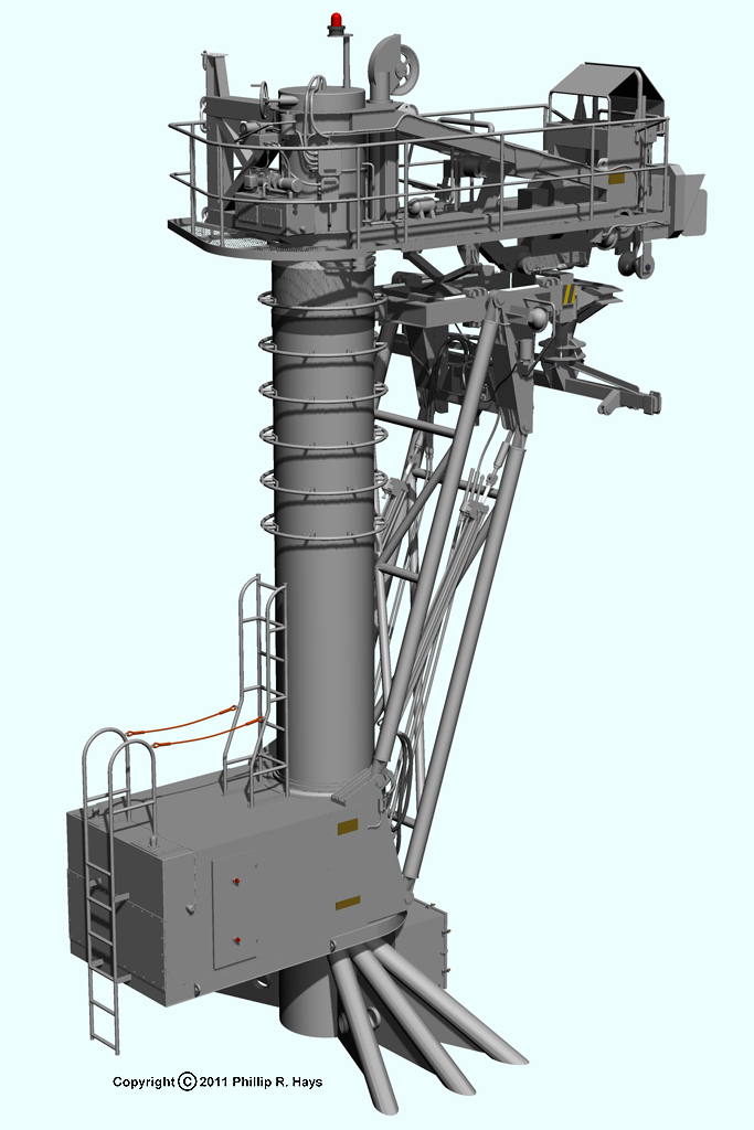
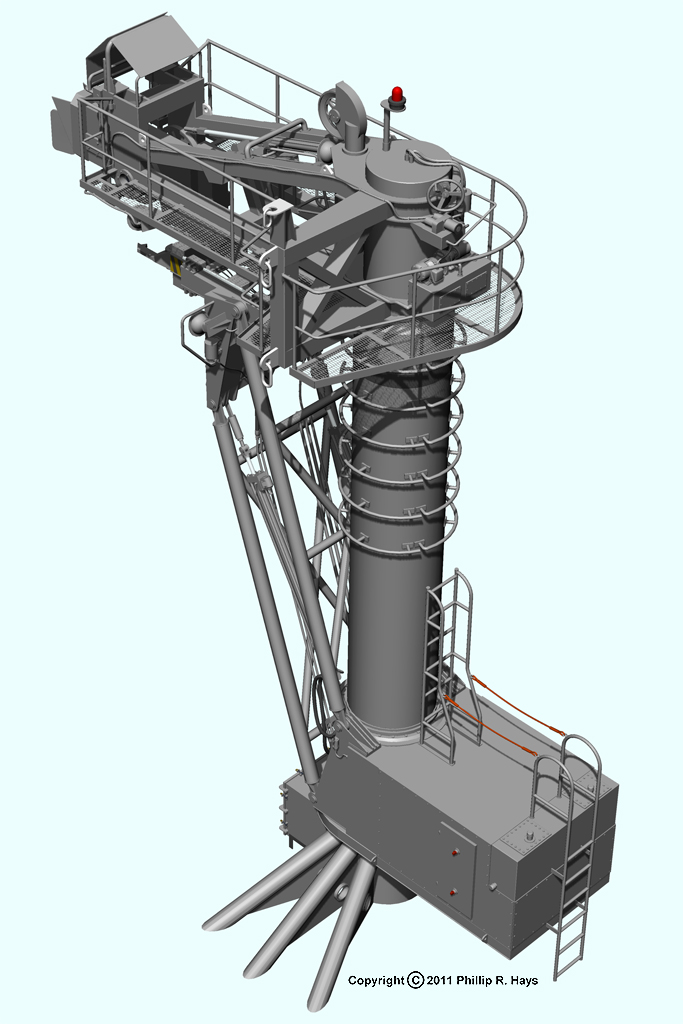
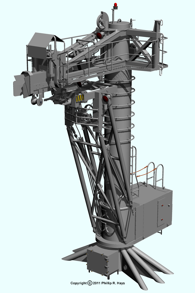
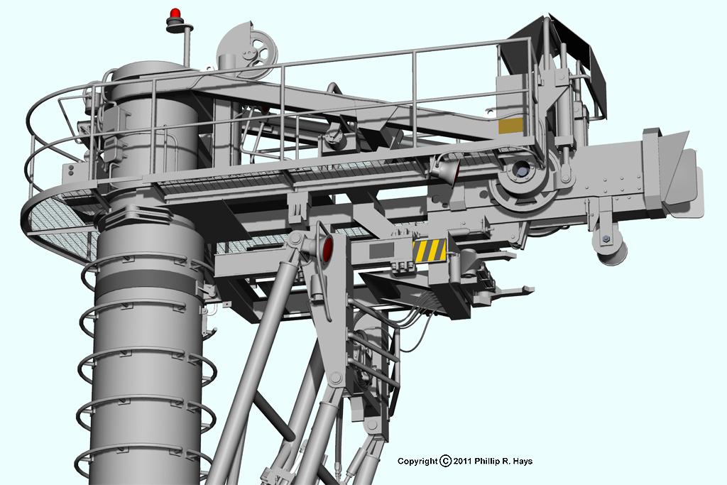
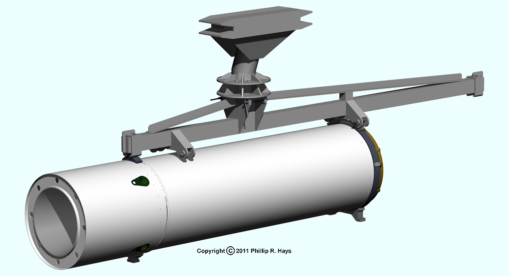
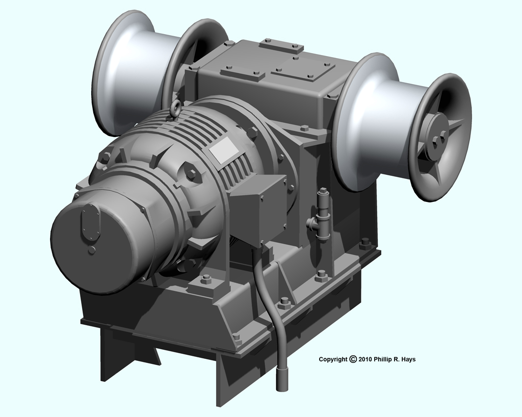
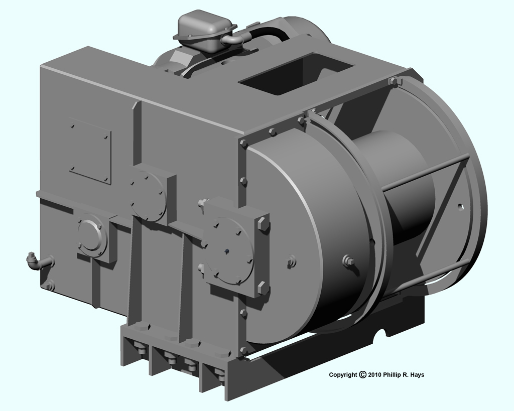
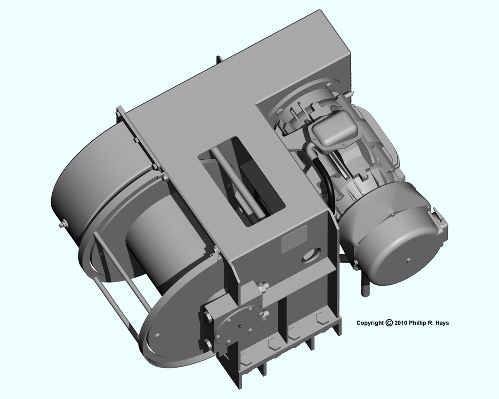
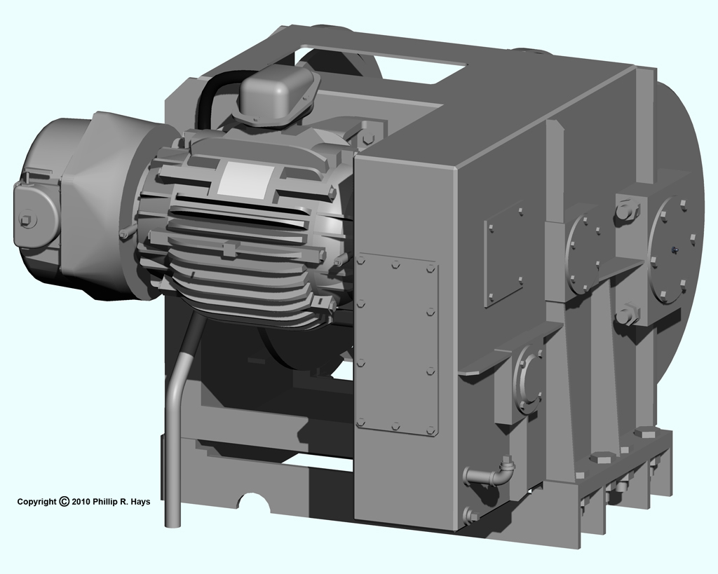
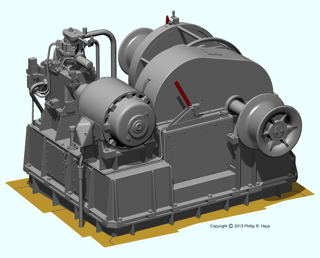
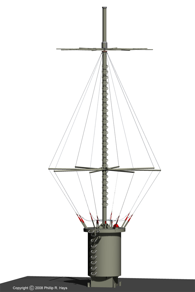
The mechanism had four major parts. At the center was a kingpost that supported the entire structure. At the top was a framework that supported a receiver mechanism. This captured a transfer cart sent over a cable from the ammunition ship. At the bottom was a cab containing pumps and hydraulic fluid reservoirs. A pantograph arm attached to the cab and supported a "claw" mechanism that grabbed a strongback missile carrier that was carried by the transfer cart. The arm then lowered the missile to a position over the missile strikedown hatch in the top of the missile house. Both the top frame and the cab/pantograph could rotate to face either port or starboard.
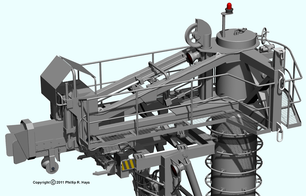
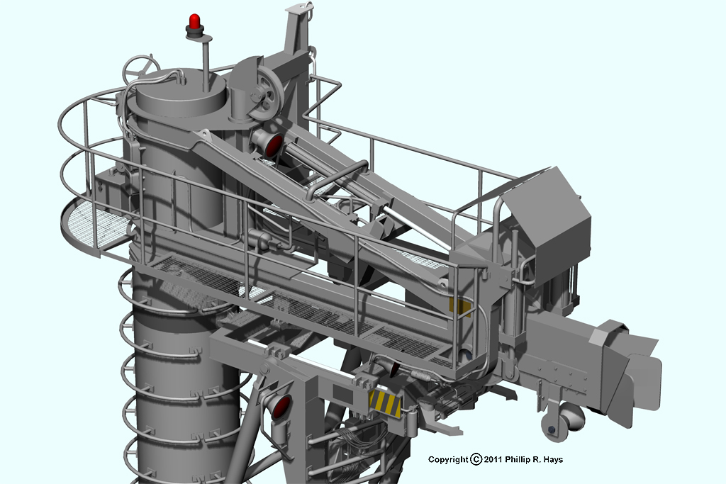
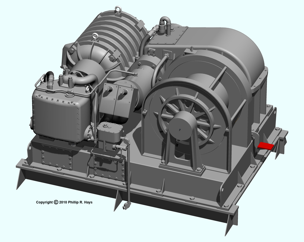
These close ups show the complex mechanisms at the top of the rig and the cab at the bottom. Again, although all of these features are visible in the photos the dimensions are pretty speculative.
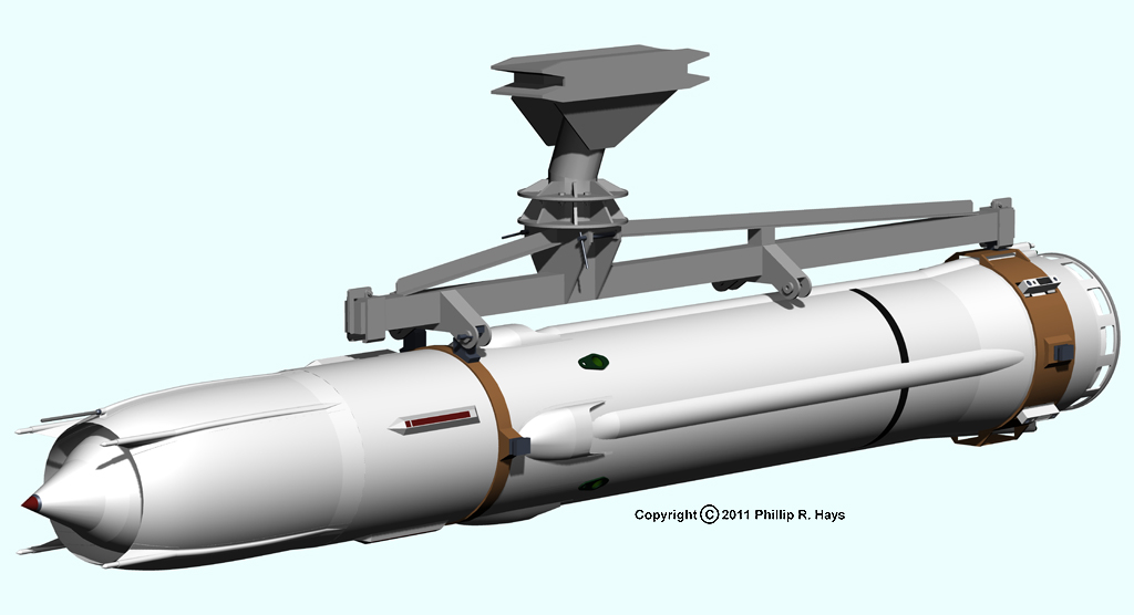
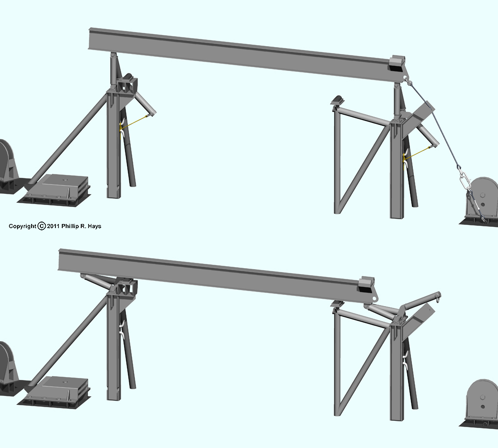
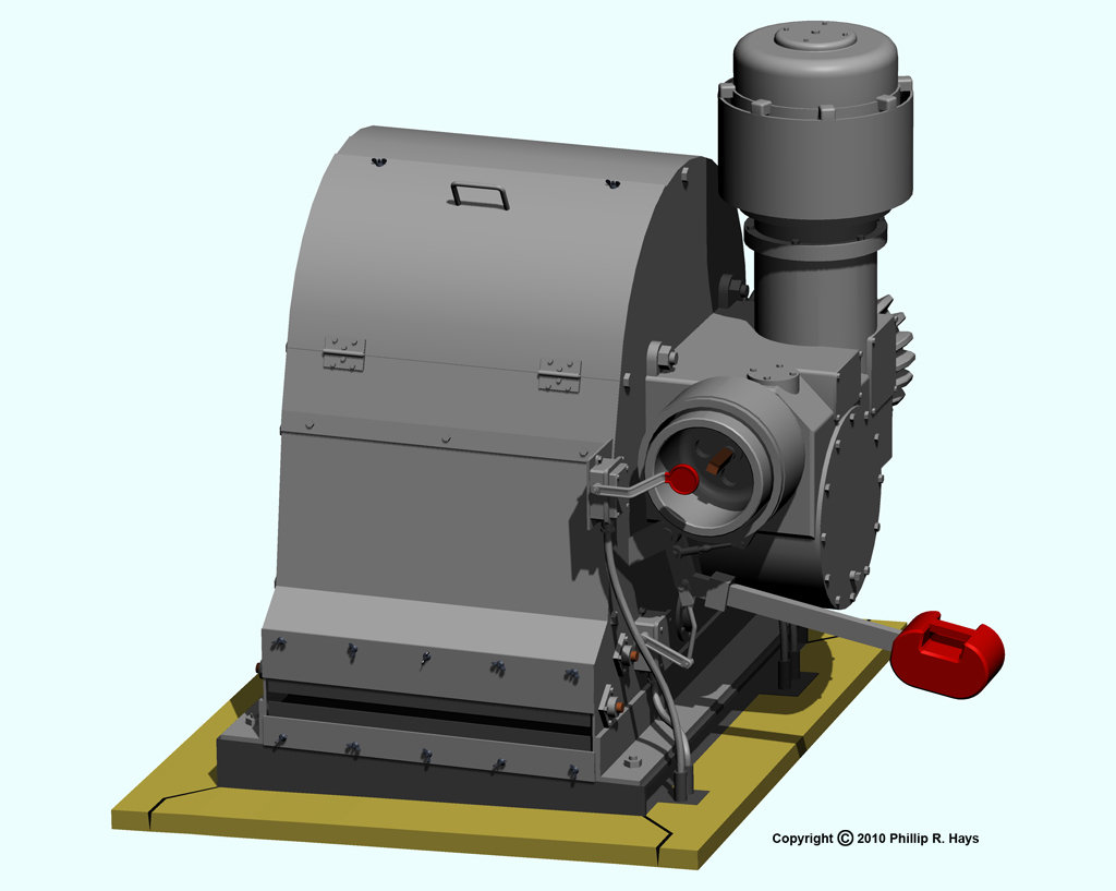
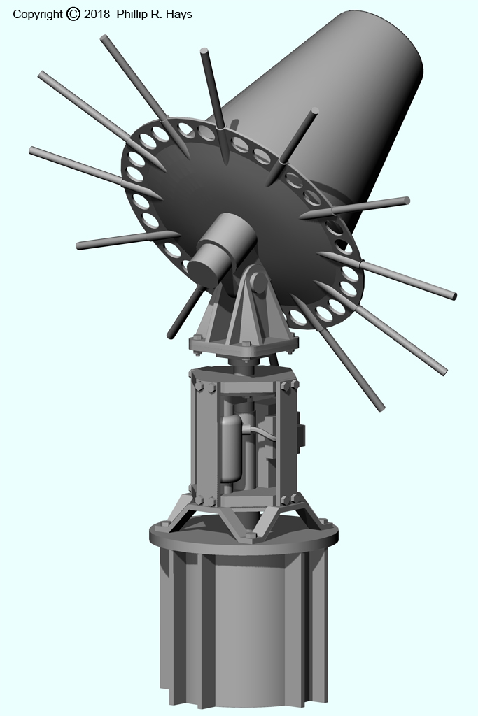
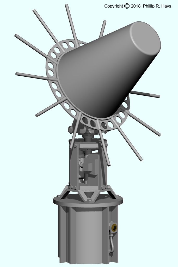
The next two pictures show the "claw" mechanism without and with the strongback attached.
Here you see the strongback attached to a missile and to a booster. It had two sets of attachment points spaced to work with either load. It captured the "shoes" on the booster that rode on the transfer rails inside the missile house. The missile attached to the booster and had no lifting points so two carrier bands with "shoes" similar to those on a booster were fastened around the missiles. The strongback used these to carry the missile. The strongback could rotate around the central part that attached to the pantograph. This allowed a missile or booster to be oriented correctly for strikedown on either the port or starboard side.
These pictures show the operation of the fast crane. An operator in a control cab (not shown) on the O2 level just forward of the missile house controlled operation of the FAST crane. Another operator inside the missile house controlled the strikedown hatch and elevator. The missile was carried to the ship by the FAST transfer shuttle. This is not shown because I have never seen it in action and I have found no drawings or photos showing the transfer shuttle. The "claw" on the pantograph mechanism grasped the strongback carrier and the shuttle returned to the supply ship to get another missile or booster. Then the strikedown hatch on top of the missile house opened and the strikedown elevator (yellow) rose to take the missile.
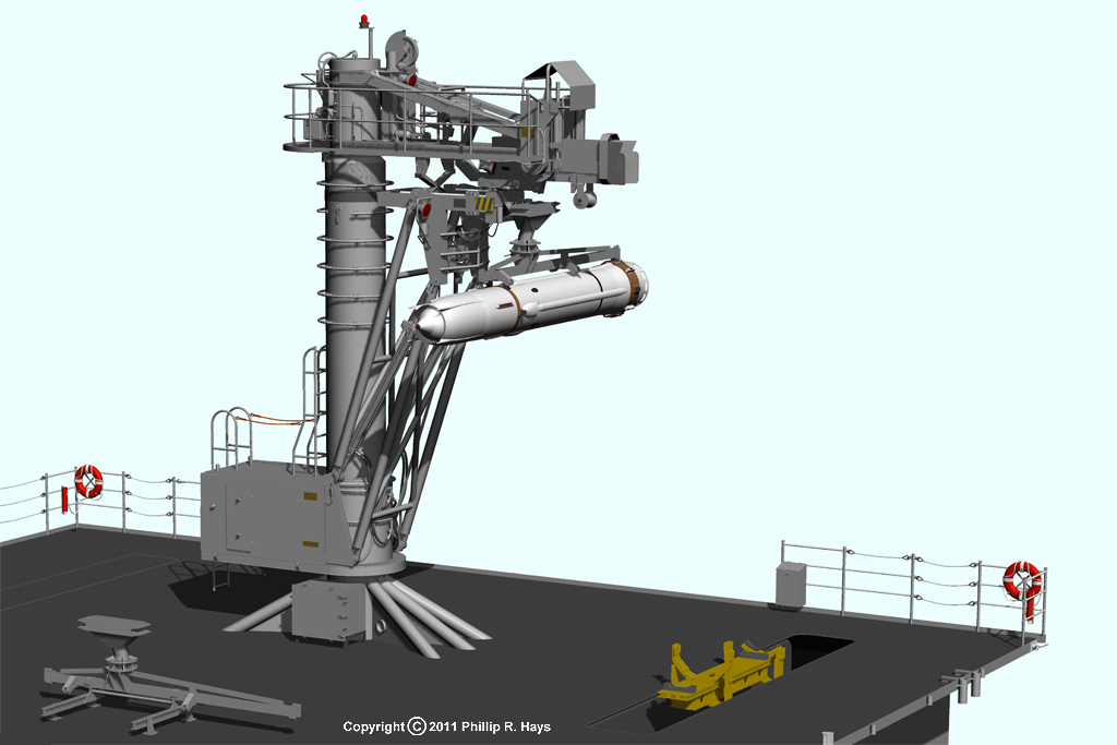
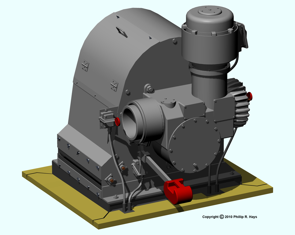
The pantograph arm was lowered, and the missile was placed into the strikedown elevator cradle. The mechanism carrying the "claw" could be moved in and out to align the missile with the center of the strikedown hatch. The strikedown elevator cradle also could be jogged fore and aft and port and starboard to facilitate alignment. Lugs on the sides of the missile carrier bands fit into receptacles on the elevator to hold the missile in position. The elevator also had a latch mechanisms to capture the shoes on the bottom of a booster. After the missile or booster was latched to the strikedown elevator the strongback attachments were released and the pantograph arm was raised. Then the strikedown elevator descended into the Area 3 Missile Stowage Magazine, the strikedown hatch closed, and the system was ready for another missile or booster transfer.
The FAST crane could also be used to move missiles and boosters between the port and starboard stowage magazines in Area 3.
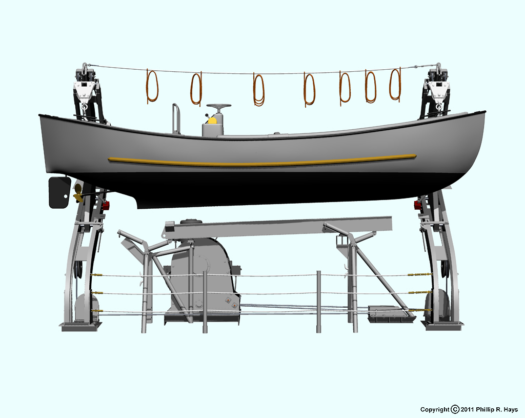
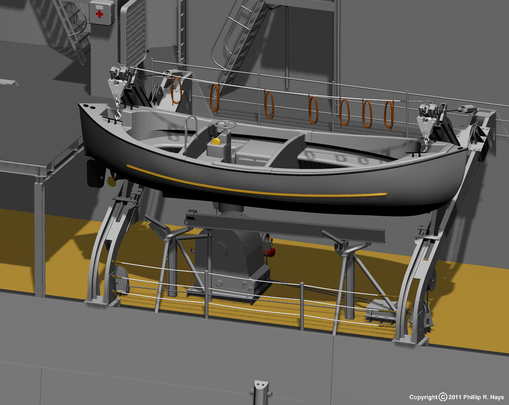
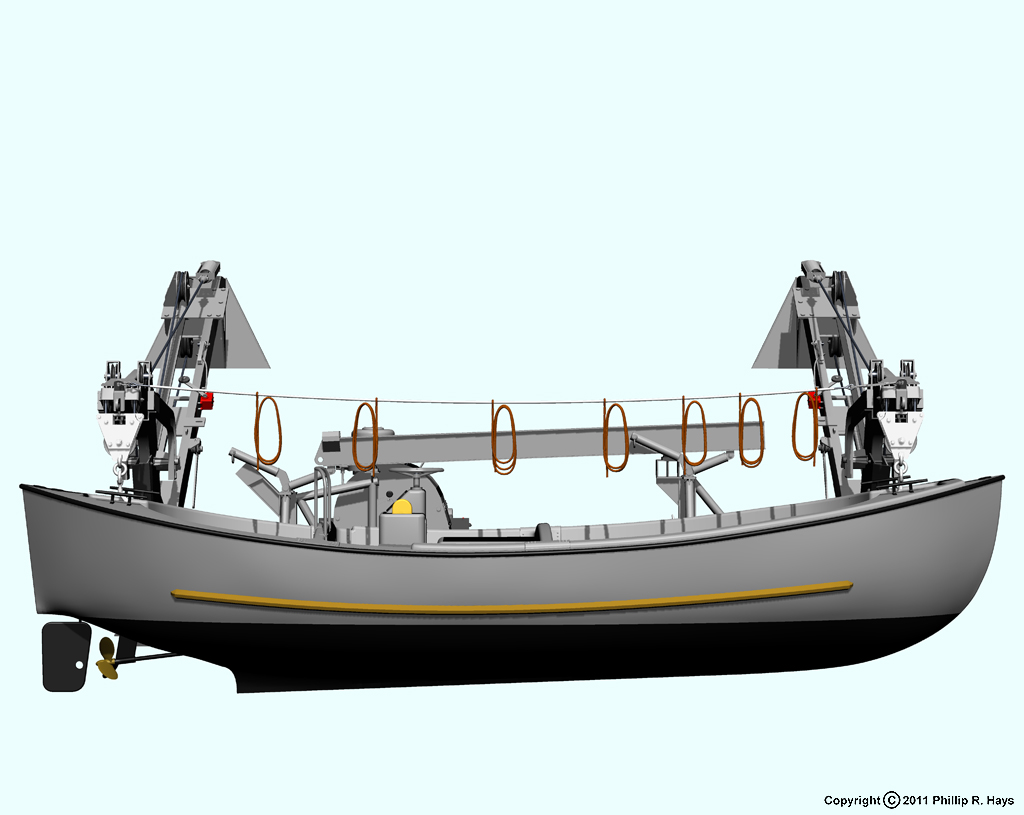
Whaleboat Davits
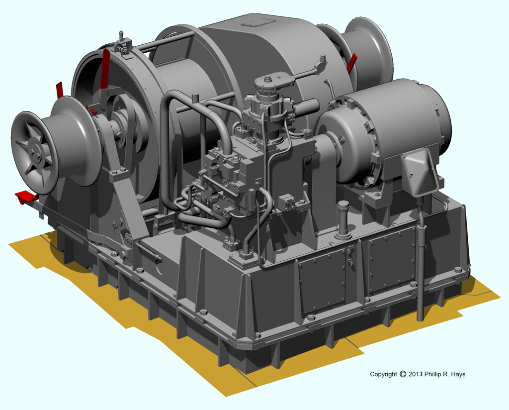
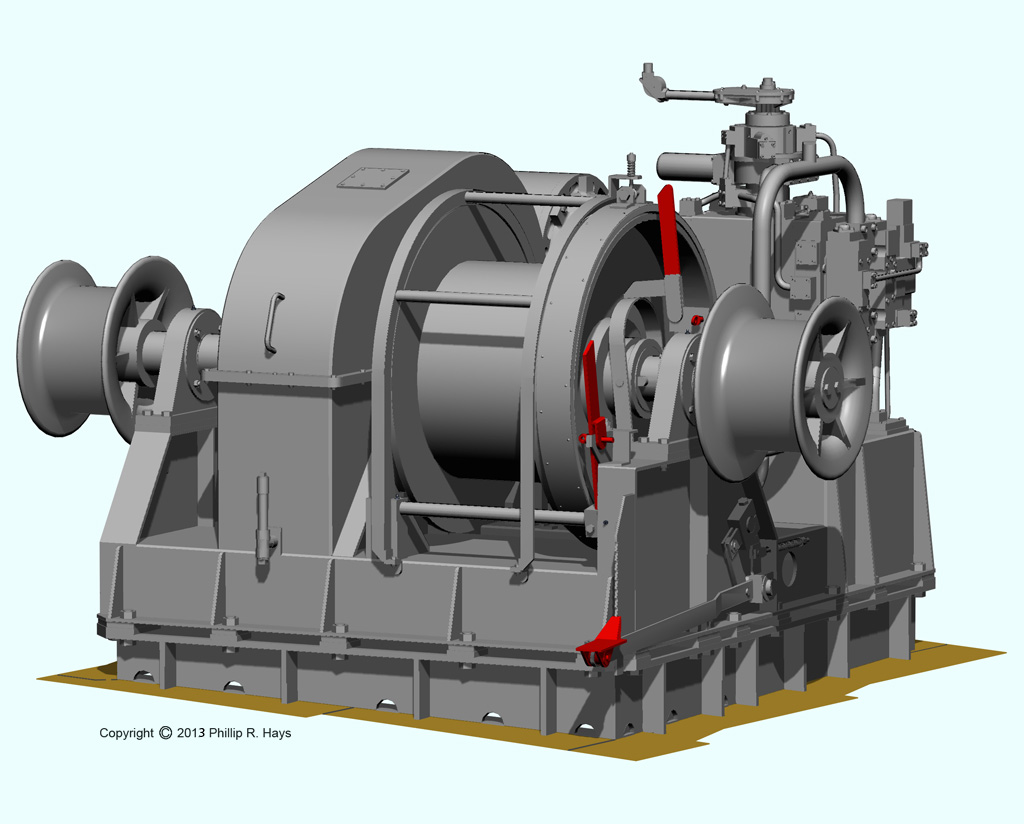
The motor whaleboat was stowed on davits on the starboard side midships. This was another photoguestimation puzzle. I have found no drawings for these davits, and I don't even know the type or Mark/Mod number for them. They were single bank, double arm, trackway gravity davits that allowed the boat to be launched without power. The boat was recovered using the whaleboat davit winch.
The davits were powered by a double drum winch with two wire rope falls (cables) that lifted the boat at both ends. The falls ran from the winch through sheaves (pulleys) on the deck and trackways, then through sheaves on the arms to the hook assembly that supported the boat. After passing through the pulley in the hook assembly the falls passed through more sheaves on the arm and then to a spring shock absorber device attached to the trackway. On the arms were weighted rotating bars called falls tensioning devices with sheaves that rested on the falls. These devices caused the hooks to be pulled up and away from the boat when the boat was released, putting the heavy free swinging hook assembly above the boat and crew. The tension was slight enough that a crewman could easily pull the hook down to attach it to the boat.
When in the stowed position the boat was secured to the davit arms to prevent it from swinging as the ship rolled. The cables that held the boat were called gripes, and typically a layer of padding called pudding was placed between the gripe and the boat to prevent chafing. The gripe had a turnbuckle that allowed the cable to be tightened to hold the boat firmly.
The gripes served two purposes. In addition to holding the boat against the davit arms, the cables also locked the levers that released the latches holding the davit arms in the raised position. When the gripes were removed and the boat was free to swing the latches were released to allow the davit arms to roll down the trackway to the lowered position.
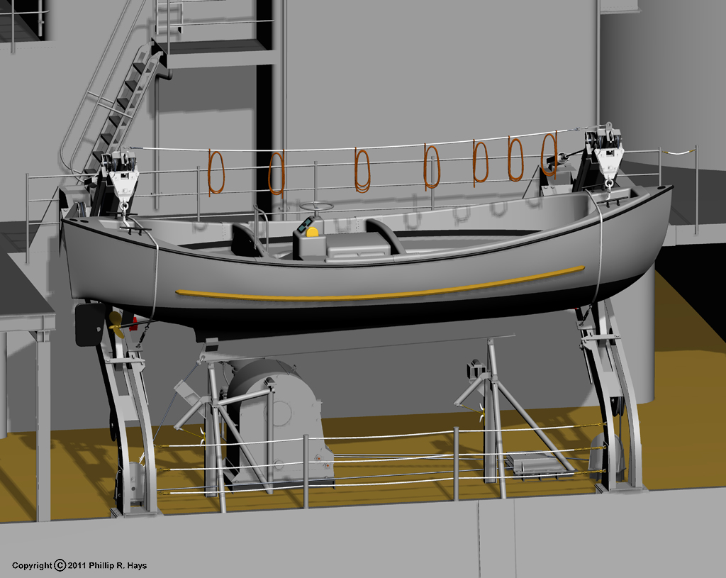
The top row of pictures show the boat stowed in the davits, with the boat support raised beneath the boat's keel and the gripes holding the boat to the davit arm. The middle row shows the boat ready for launch with the support lowered and the restraining gripes removed. The bottom row shows the davit arms in the lowered position with the boat swung out over the ship's side.

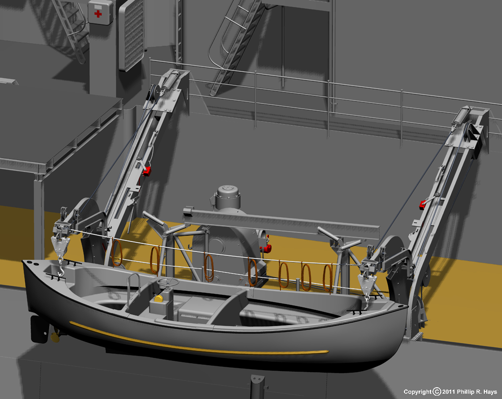
After the davit arms were at their lowest position with the boat swung over the side in the launching position the falls were let out by the winch to lower to boat to the water. Additional lines were used to control boat swinging, and another line called a painter lead from the bow of the boat to a sailor on deck who held the boat in position alongside the moving ship. Before the boat entered the water the motor was started so the boat would have maneuverability as soon as it entered the water.
The coiled ropes suspended above the boat were man ropes or monkey lines. Each person in the boat held one of these ropes as the boat was lowered to the water. If something went wrong and the boat dropped into the water the crew could pull themselves back up to the ship's deck with these safety lines. The ropes had knots tied in them every foot or so (not shown) to make it easier to climb.
When in the stowed position the whaleboat was supported on an I beam keel rest. The beam was attached to two pivoting arms that allowed the support to be lowered away from the boat. Each pivoting arm was tied in the up position with a lanyard wrapped around a cleat. In addition, a cable ran from the aft end of the I beam to an attachment on deck.
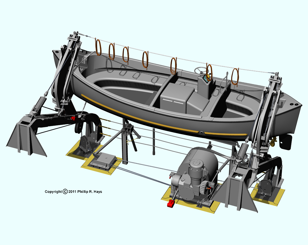
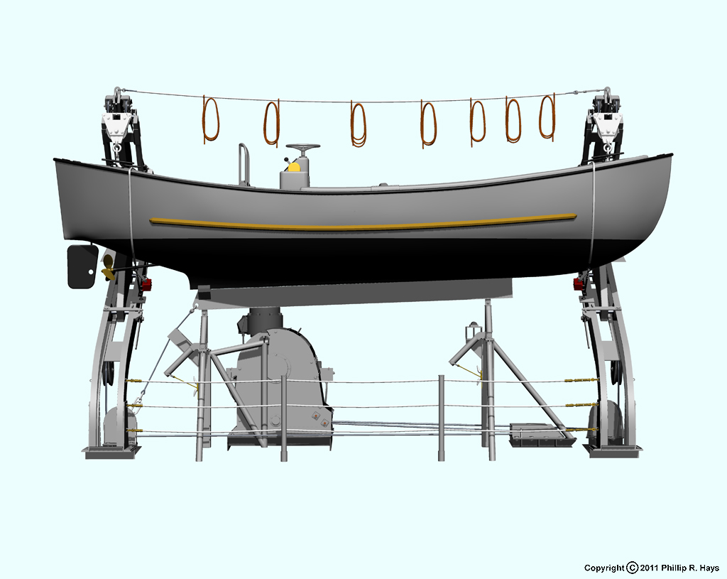
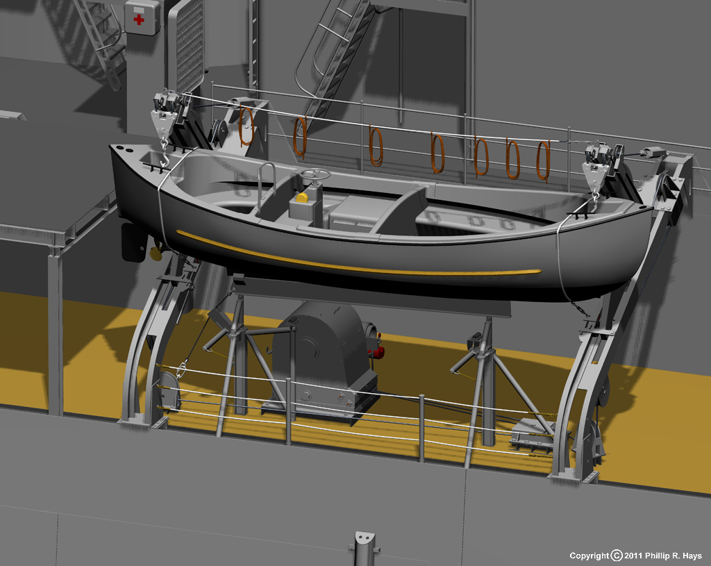
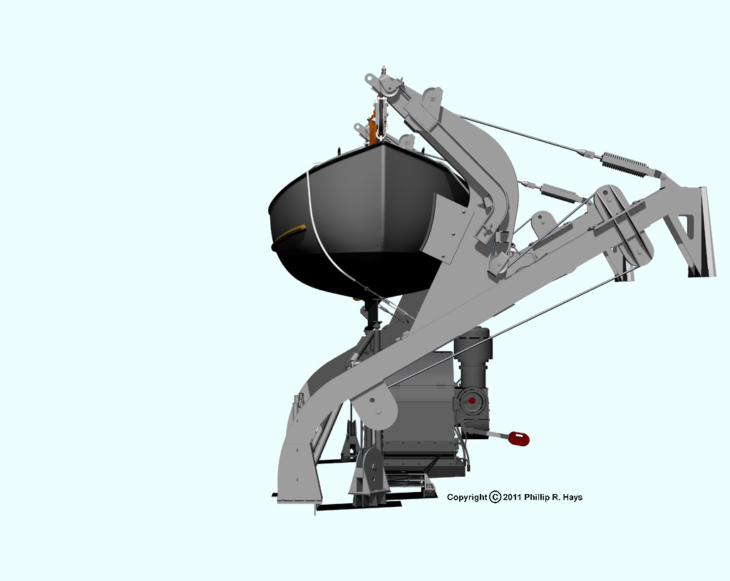
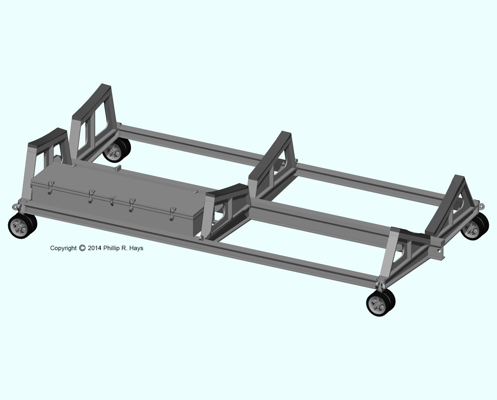
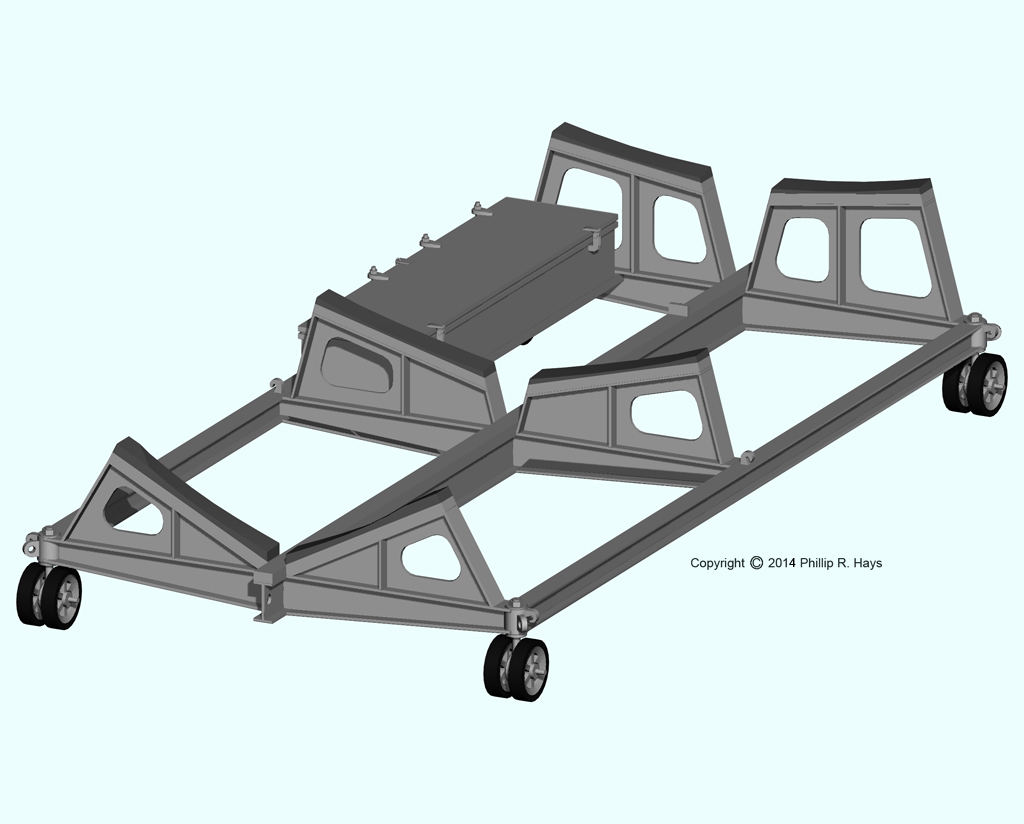
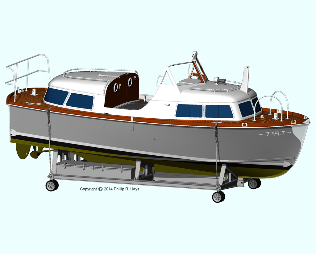
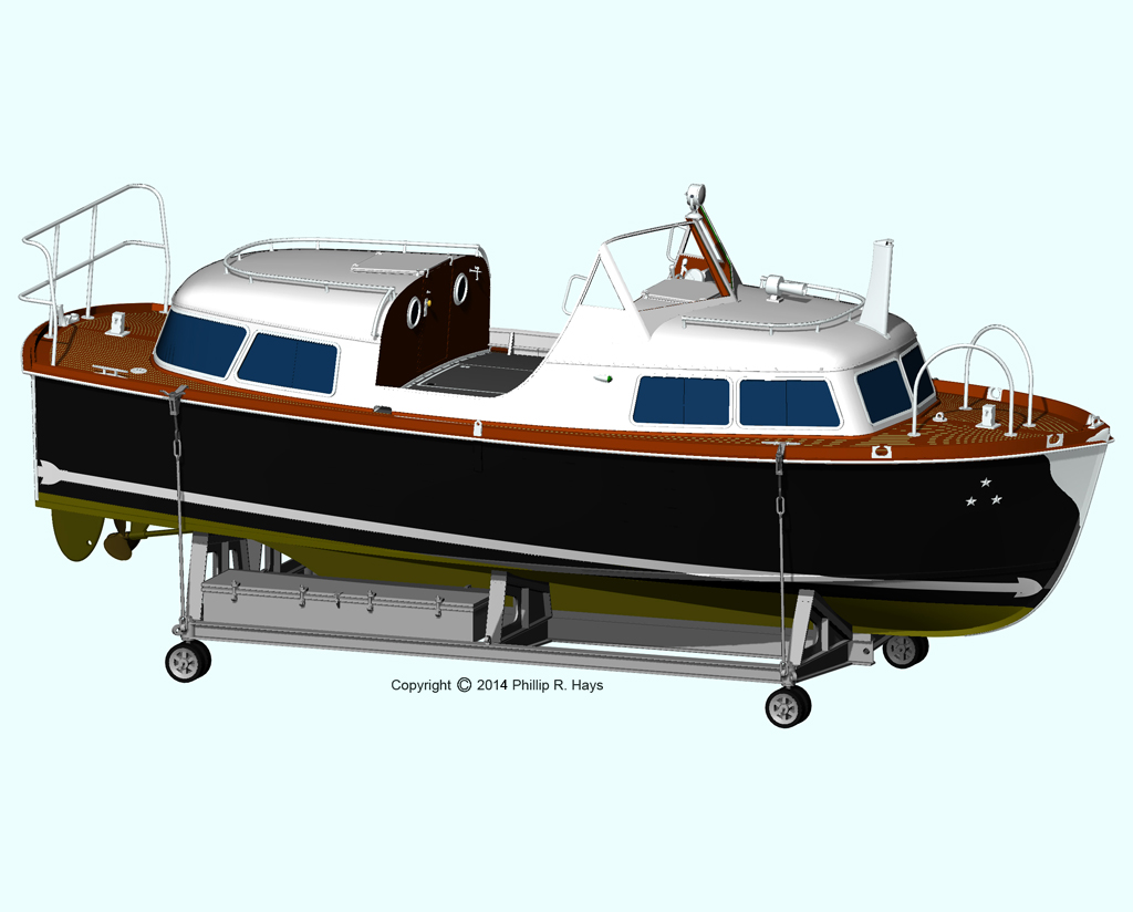
28 Foot Personnel Boat Cradles
The 7th Fleet 28 foot personnel boat and the Admiral's barge 28 foot personnel boat were stowed in portable cradles on top of the missile house. The 7th Fleet boat was usually on the port side aft and the Admiral's barge usually was on the starboard side aft. The cradles were moved forward to the front of the missile house with the snaking winches. From there the boats could be lifted out of the cradles and lowered into the water using the kingpost booms.
I am pretty sure the cradles had diagonal bracing, but I have no plans or photos showing the arrangement.
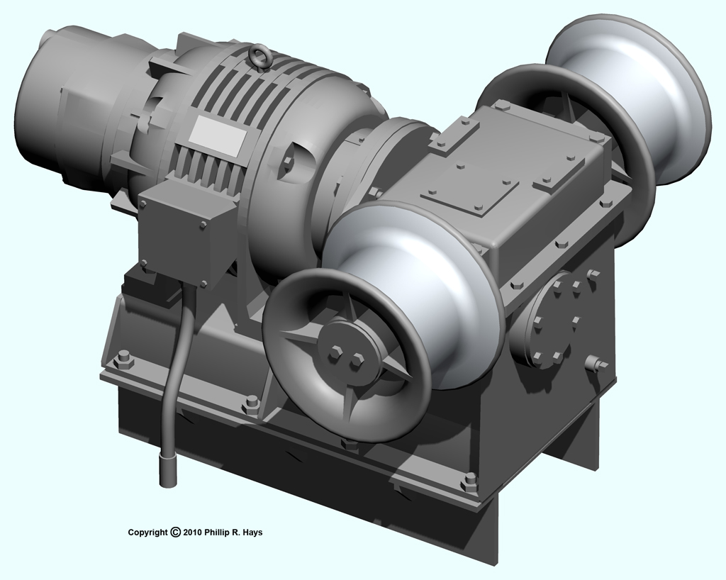
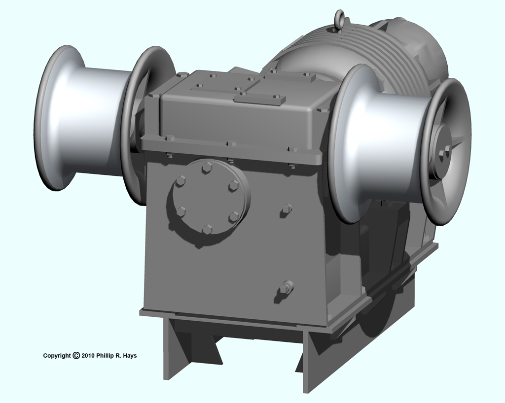
Winches
There were five different types of winches on the ship.
Snaking Winch
There were two snaking winches on top of the missile house. They provided power to move a variety of heavy objects. They were also used to lower or raise missile warheads through the warhead strikedown hatch above the missile test cells and the Special Weapons Office.
Topping Winch
The two topping winches raised and lowered the large booms attached to the kingposts. These booms were used to move boats in and out of the water and to hoist heavy objects onto the ship. The large boat winches provided the lifting power for raising and lowering objects.
Whaleboat Davit Winch
The whaleboat winch was used to lift the whaleboat out of the water and hoist it into position on the boat davits. The winch could be operated manually with a hand crank in case electrical power failed. When the crank was installed it opened a safety interlock switch that prevented the winch motor from being energized.
Boat Winch
The large boat winch was used to raise the ship's boats from their cradles and lower them into the water, and vice versa. It was also used to move heavy objects to and from the top of the missile house. The Admiral's barge and the 7th Fleet boat were stowed there on moveable cradles. On some occasions automobiles were stowed on top of the missile house.
The winch also had two gypsy heads and could be used to haul on mooring lines and other ropes.
Burtoning Winch
The burtoning winch was the heavy lift machine used for UNREPS transfers. It was aligned for transfers on the starboard side, with the burtoning whip block (pulley) attached to the FAST kingpost on top of the missile house. The burtoning whip (cable) ran through this pulley and attached to a swivel block that carried the load. Another burtoning whip from the supply ship connected to the other side of the swivel block. Burtoning winches on both ships were operated simultaneously to let out and take in cable so the swivel block moved from one ship to the other. Visual signals were used to coordinate winch operation on both ships. First the load was lifted from the supply ship deck by that ship's burtoning winch. Then the load was transferred to Okie Boat. When in position over the OK City's deck the load was lowered to the deck with the OK City's burtoning winch.
Antennas
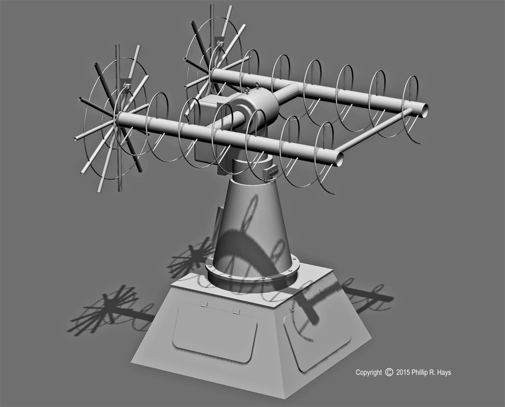
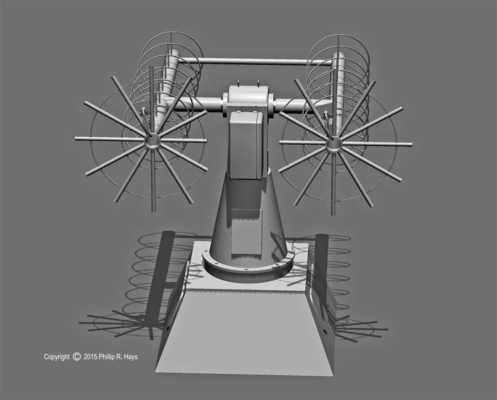
The ship was an antenna farm. The AN/SMQ-6 weather satellite antenna (left, with the two helical elements) was on top of the pilot house. The ship received satellite data several times a day.* The large AN/SRA-57 discone (or discage) radio antenna (right) was located on the bow, away from potential sources of disturbance on the ship. The crew referred to the cylindrical stowage compartment at the base as the "beer can."
The AS-979/UKR was a telemetry antenna. It was mounted at the rear of the after radar tower. I think it was the antenna used to receive telemetry information from Talos missiles in flight, but I am not certain. It was installed on all Talos ships in close proximity to the SPG-49 and SPW-2 antennas.
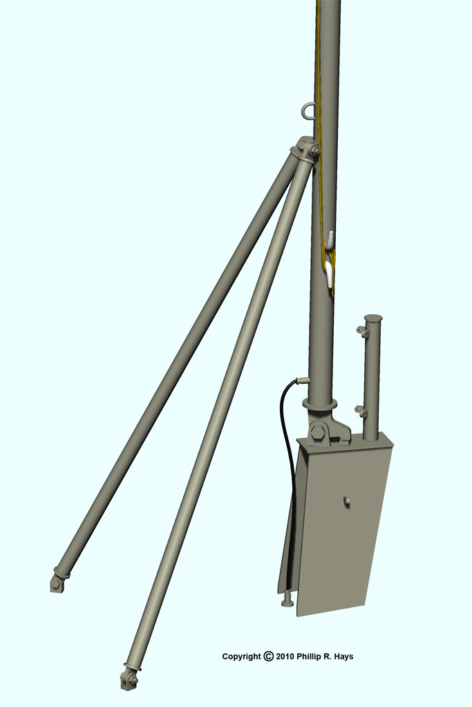
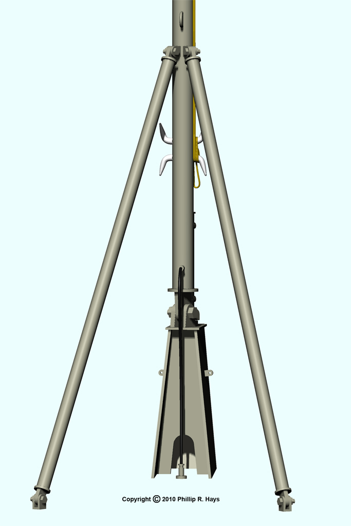
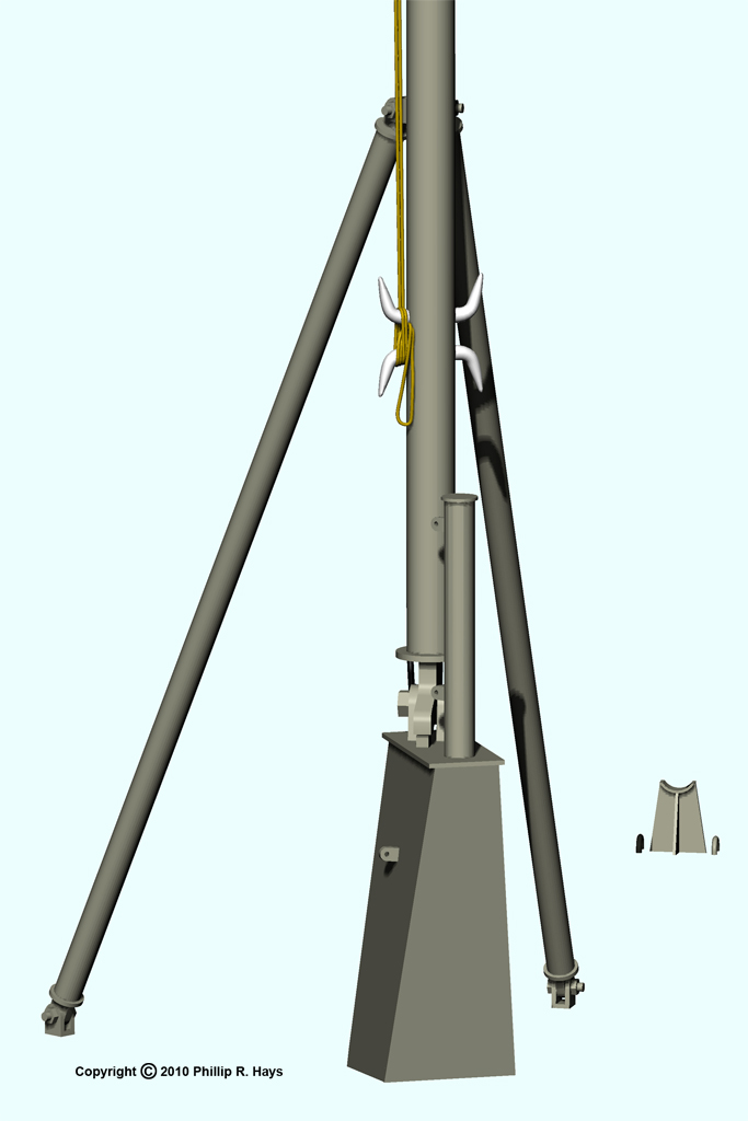
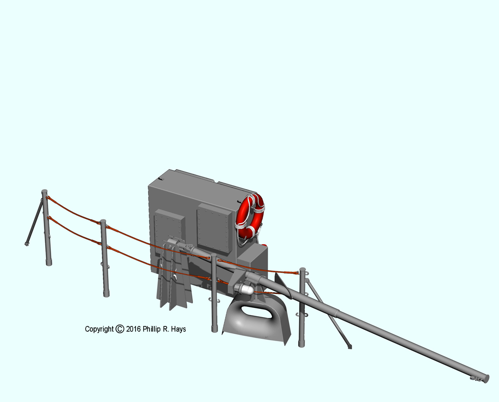
Jack Staff and Flag Staff
The Union Jack flew from the jack staff when the ship was not underway. A white anchor light was at the top of the staff. The base of the jack staff appears with an open front in early photos. Later this was covered with the plate shown in these images. Lifelines attached to the short post in front of the staff. The jack staff was hinged down and lashed into a cradle welded to the deck when the ship was underway.
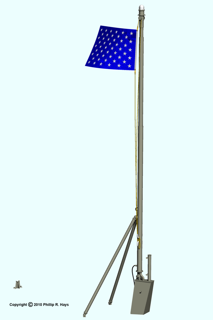
When the ship was not underway the United States flag was flown from the flag staff at the stern. At sea the flag flew from a gaff at the top of the fore tower.
The flag staff existed in three versions. The first was installed in the shipyards in 1959, and was very short with no diagonal supports. A taller version was installed during the yard period in 1963. It fit into a socket on the deck and had two diagonal supports that fastened to anchors on the deck. The third version shown here was installed in 1969. It was supported on the tall pillar with braces attached to the electronics cabinet just forward. The flag staff was stowed in a cradle welded to the top of a nearby chock when at sea and while conducting flight operations in port. The flag staff carried the stern white anchor light.
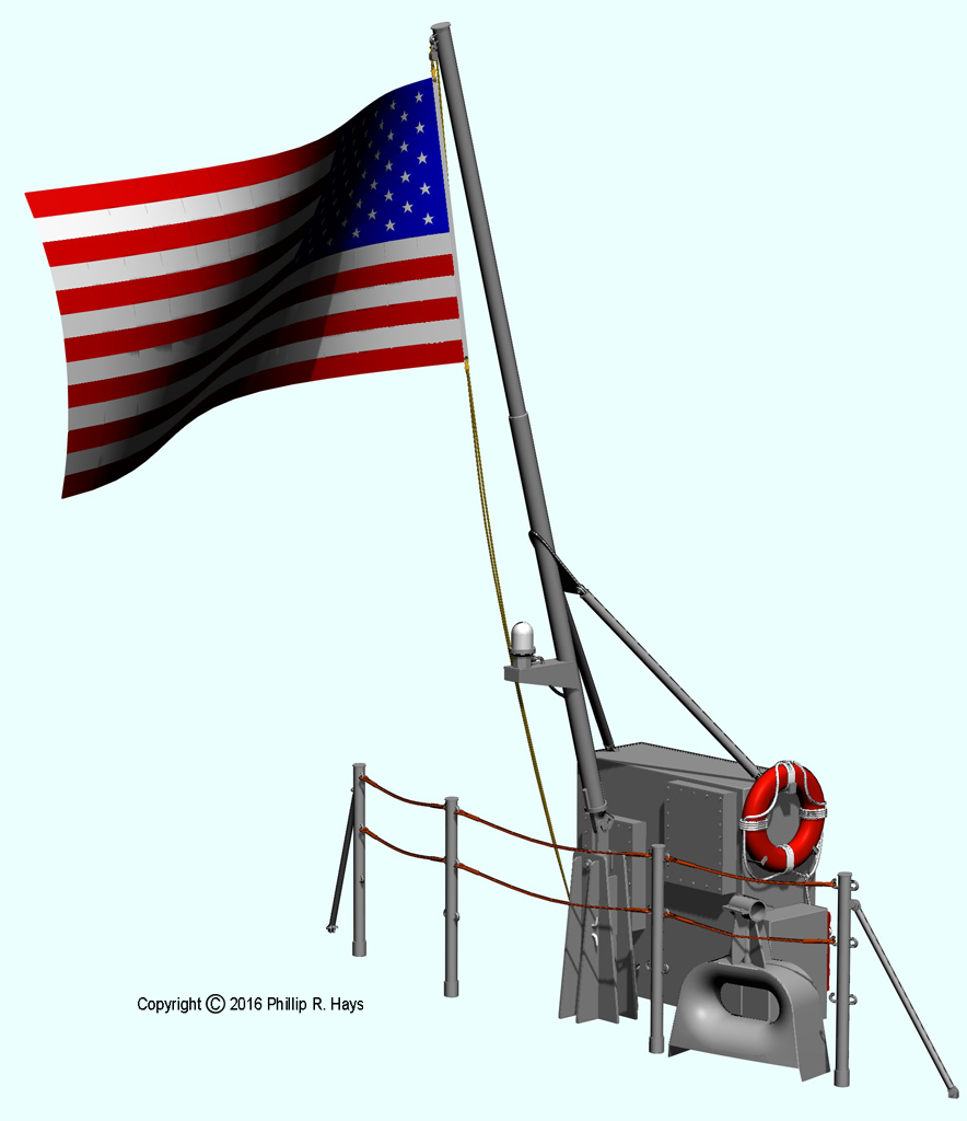
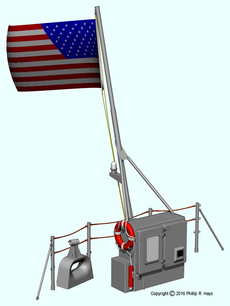
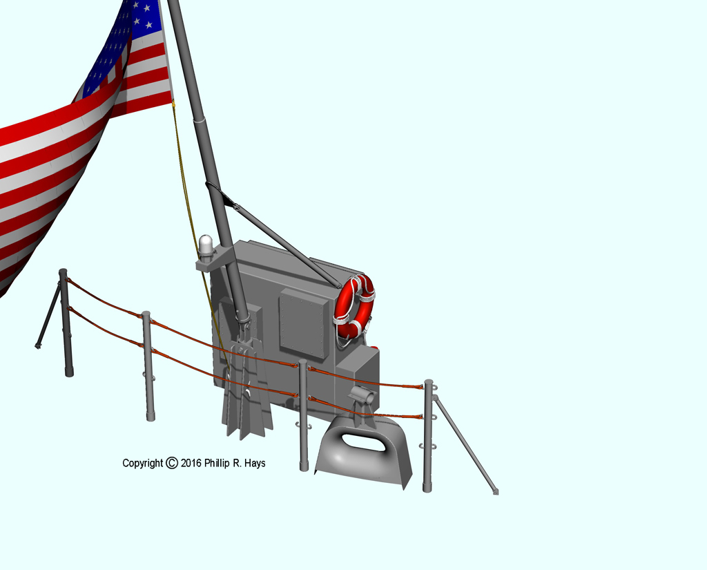
The flag staff was one of the most difficult parts of the ship to model. I have found no drawings of this third version, and I have few photos that show it clearly - there aren't many photos of the stern of the ship. This is a revised version using better photos and dimensions from the original flag staff that is now at the American Legion Center in Newport, Oregon.
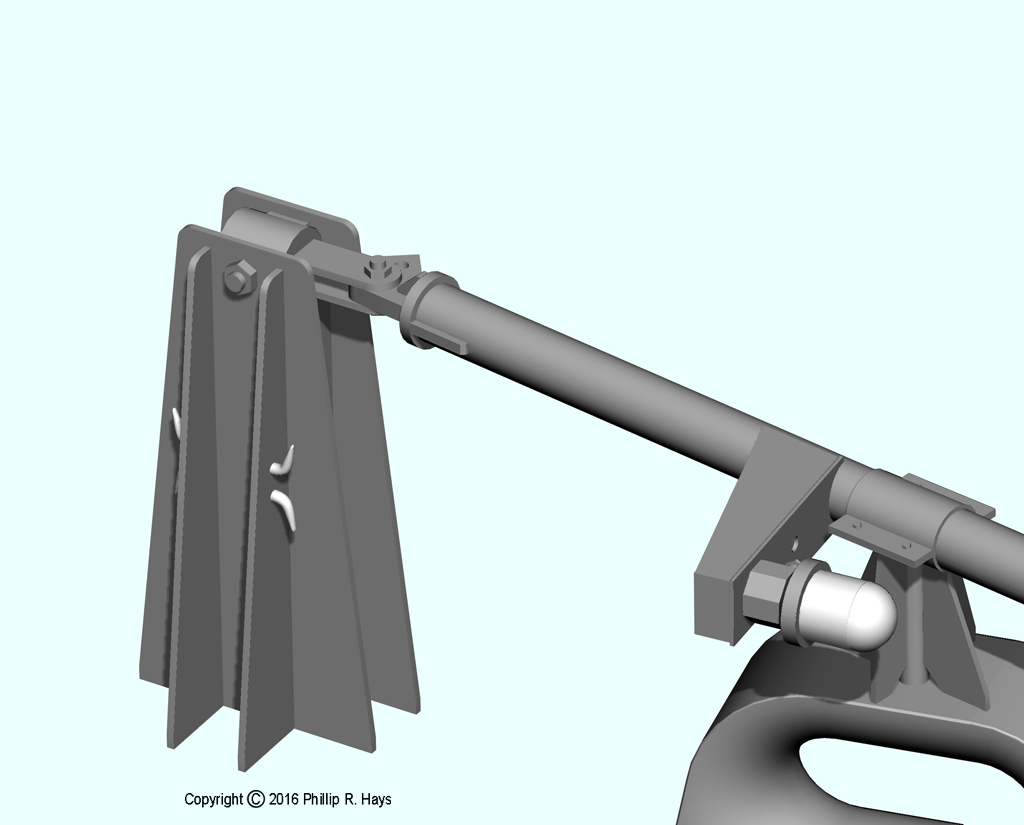
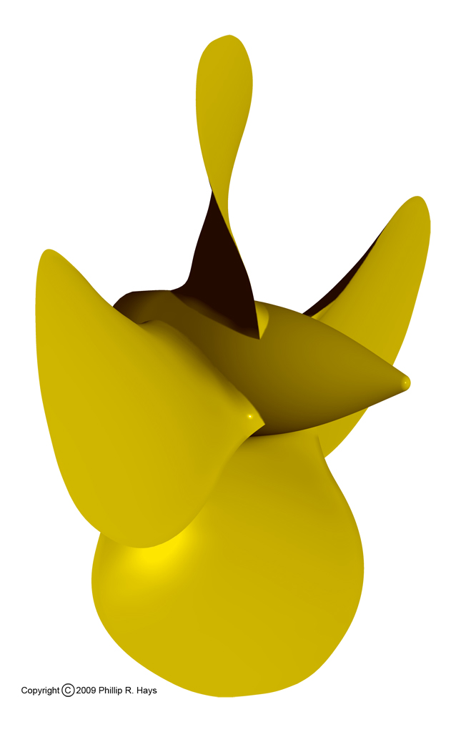
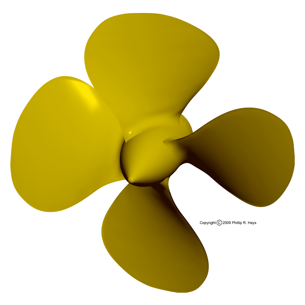
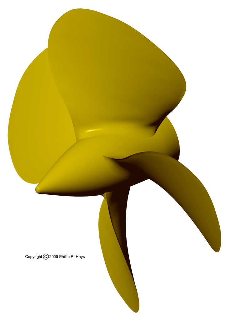
Propellers and Propeller Struts
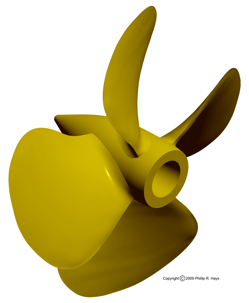
The propellers were an interesting modeling project. They were "proportional pitch" propellers with the angle of the blade (relative to the centerline of rotation) changing with the radius from the center to achieve relatively evenly distributed forces on the blades. The farther out from the center the greater the rate of motion through the water. Close to the center of rotation where the blade is narrow it is angled sharply to the direction of rotation to achieve greater force on the water. Farther out the angle of attack is much less where the blade is widest. I started with the original blueprints and built up the blade through several iterations to get the correct proportional pitch.
The propellers were eleven feet ten inches in diameter and weighed 14,930 pounds each. The ship actually had four different propellers. The starboard propellers had right hand pitch (turned clockwise for forward motion) and the port side props had left hand (counterclockwise) pitch. The inboard ("A") and outboard ("B") propellers were slightly different designs to produce equal thrust from each propeller. They had the same diameter but the blades were about 1% wider (perpendicular to the axis of the blade) on the outboard "B" props. These were higher in the water (slightly lower water density) and the wider blades increased thrust to compensate. The inboard propellers were deeper in the water (greater water density) so slightly smaller blades were used.
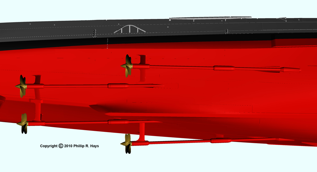
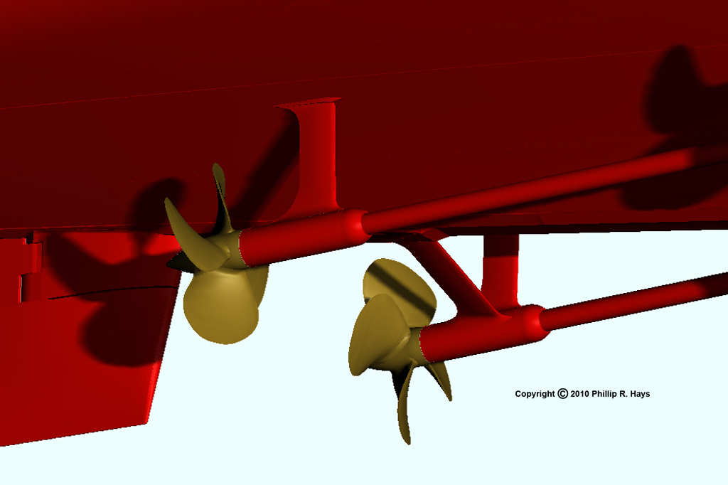
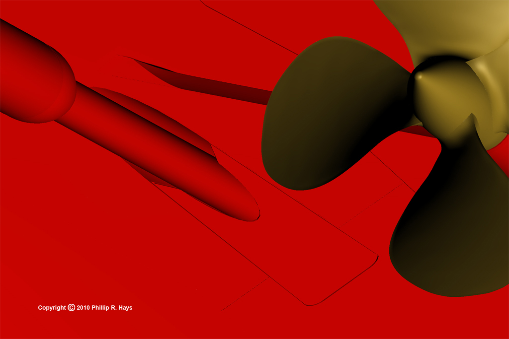
The propeller shafts passed through shaft tubes in the hull and were then supported by two struts under the hull. The after struts were massive single steel castings with a tube 2 1/2 feet in diameter almost 7 feet long, with legs 10 to 12 feet long. The forward struts had similar tubes and one short leg. After the struts were installed on the ship the tubes were bored in place to carry bearings for the shafts. The legs of the struts were machined to a low drag "airfoil" shape, with a slight twist from the hull to the strut tube. The twist was calculated to match the direction of water flow around the hull to minimize drag. Separate fairwaters fit around the shafts to streamline the ends of the strut tubes.
About 80 feet of shaft extended outside the hull. The shafts were assembled in sections that were bolted together with flanges at the ends. The sections could be separated and removed from the ship for repairs. All four shafts had sections about 50 feet in length between the forward and aft struts with joints inside the fairwaters at the forward end of the forward strut. The inboard shaft had another long section forward of the first with a flange inside the ship just ahead of where the shaft tube penetrated the hull. The outboard shaft had a shorter second section with the flange joint outside the hull in the shaft tube aft of where the shaft penetrated the hull. The shaft tube openings were covered with portable plates that served as fairwaters. The inboard plate was a simple plate that fit flat over the opening. The outboard portable plate had raised conical sections that fit around the shaft coupling.
Odds and Ends
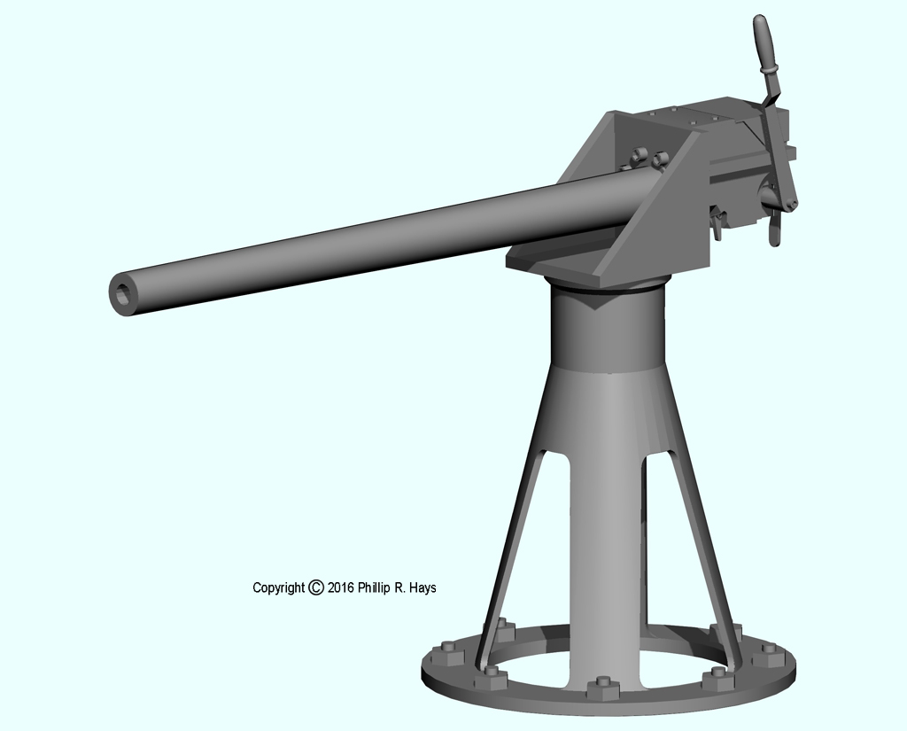
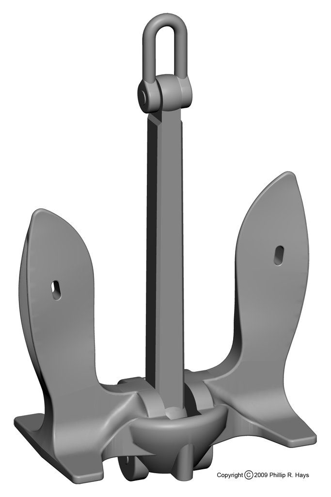
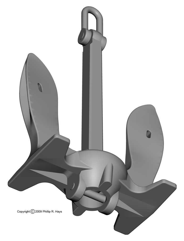
The saluting gun was used for ceremonial occasions. It fired a 37mm blank cartridge. The wildcats were the mechanism used to raise and lower the anchors. They were essentially large chain sprockets. The anchor weighed 13,000 pounds, was six and one half feet wide and over eight feet tall.
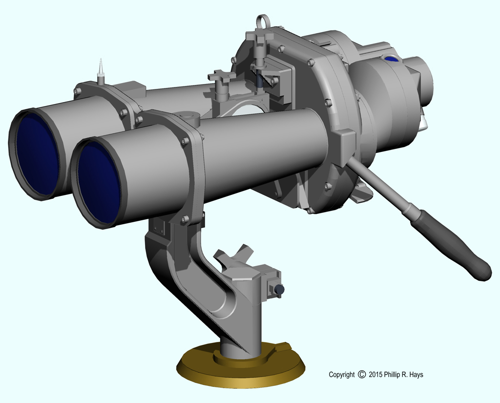
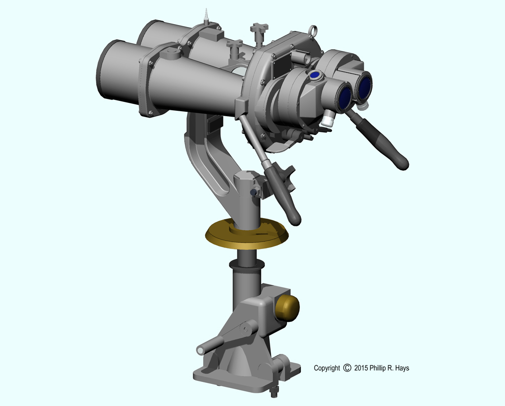
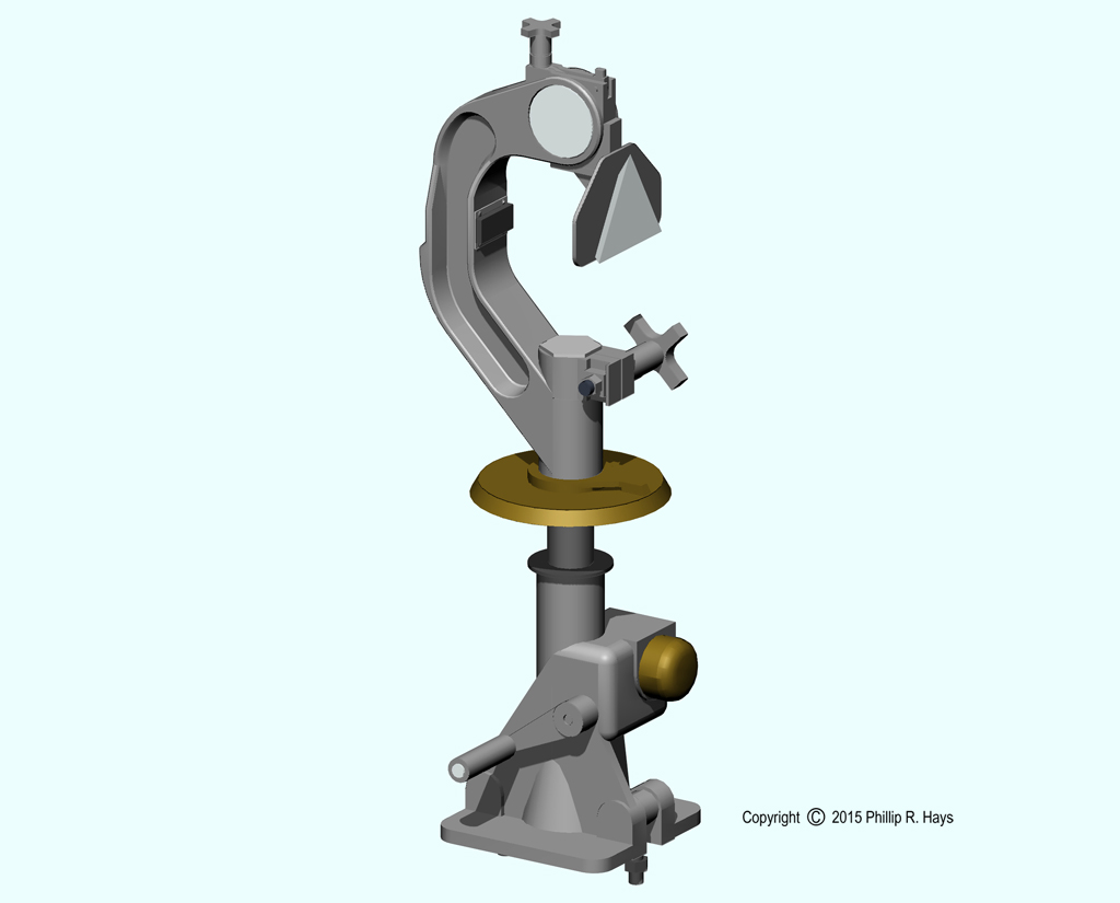
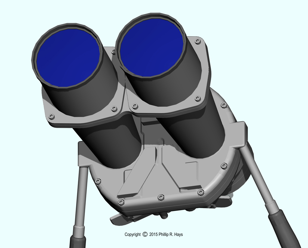
The ship carried large Kollmorgan 20x120 binoculars on the O4 level of the forward superstructure. The binoculars fit onto a stand that had an elevation crank to adjust height. A bearing circle below the binoculars allowed the user to report the relative bearing of objects being observed. The binoculars were a separate assembly, with a socket that fit over the triangular feature near the top of the stand. When not in use the binoculars were stowed inside.