

One day in the fall of 2003 my oldest son casually asked if I had ever made a model of the Okie Boat. I said that someday I might build one but I had never seen a kit, or even good plans for the ship. He knew I had built several models of sailing ships, so it didn't seem like an unusual question. That Christmas, after everyone had opened their gifts, he stepped out of the room when I wasn't watching and came back saying there was one more present, and it was for me. Leaning against the wall was a gift wrapped present about eight inches square and seven feet tall. "They got me skis?" I thought. Wrong! It was a 6 1/2 foot long fiberglass 1:96 scale hull for a Cleveland class cruiser. Inside was a single sheet of deck plans. The rest was do it yourself.
I have always wanted to build a model of the ship, and this was the push that got me started. I immediately began gathering all the information I could find about working with fiberglass hulls. The hull came from The Scale Shipyard and a lot of additional parts and plans were available from this source. I found several other sources of plans in the Internet, and The Floating Drydock was one of the best. I ordered several sheets of plans and started figuring out how I was going to build the thing. I eventually ordered microfilm containing thousands of original blueprints from the National Archives, and have prepared my own drawings from these. In fact, this led me to create a 3D CAD model (Computer Aided Drafting) of the ship to learn how all the parts fit together. It has developed into quite a project. This page shows the steps I have completed so far in the real model. There is still a long way to go!
The Hull Shaping Frame
The first thing I built was a frame to keep the thin fiberglass hull in the correct shape while I was working on it. The thin fiberglass was quite flexible and the out-of-the-box shape was too narrow at places, and the curvature at the stern was not correct. This isn't a criticism of the hull manufacturer. Long thin hull shells are very flexible and change shape during shipping and handling. They can also twist along the long axis. Murphy's Law says it will happen if it can happen. An "anti-Murphy's" framework is needed to hold the shell in the proper shape before internal framing is attached.
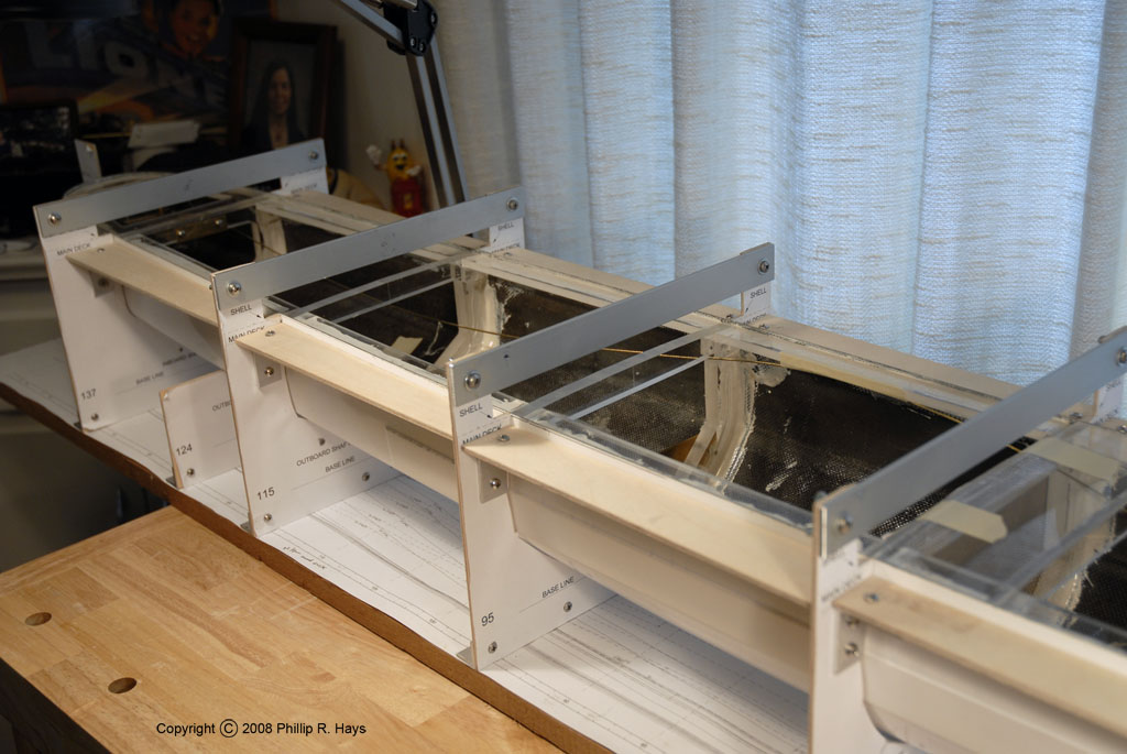
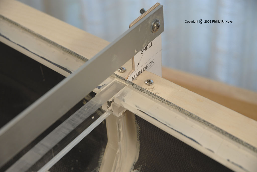
This frame was constructed on a 1" x 12" board 7 feet long. I plotted a 1:96 scale drawing of the hull top view and taped it to the board. This drawing showed the hull outline, butt lines and water lines. It also had frame markings along the keel and a set of drawing scales. I screwed 3/4" aluminum "L" brackets to the board, positioned perpendicular to the keel at eight positions along the drawing. To these I attached plywood templates that were shaped to match the hull cross section at the particular frame. On these were drawings of the hull cross section. Across the top of these I used thumbscrews to attach 3/4" x 1/8" aluminum bars to keep the tops of the templates from spreading. These could be removed and replaced easily to allow free access into the hull.
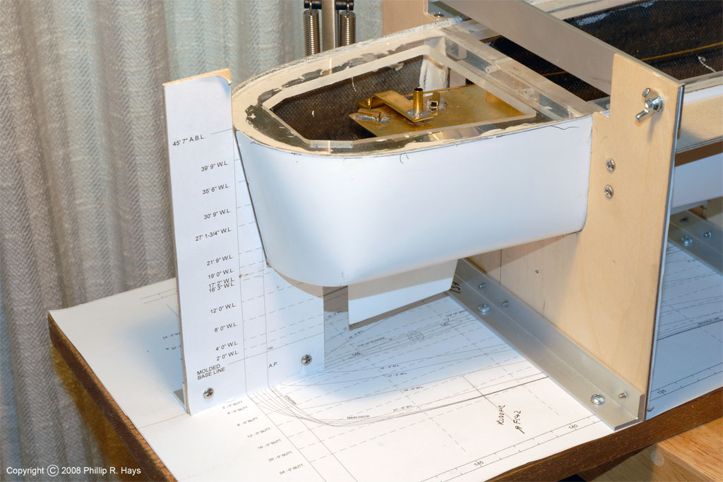
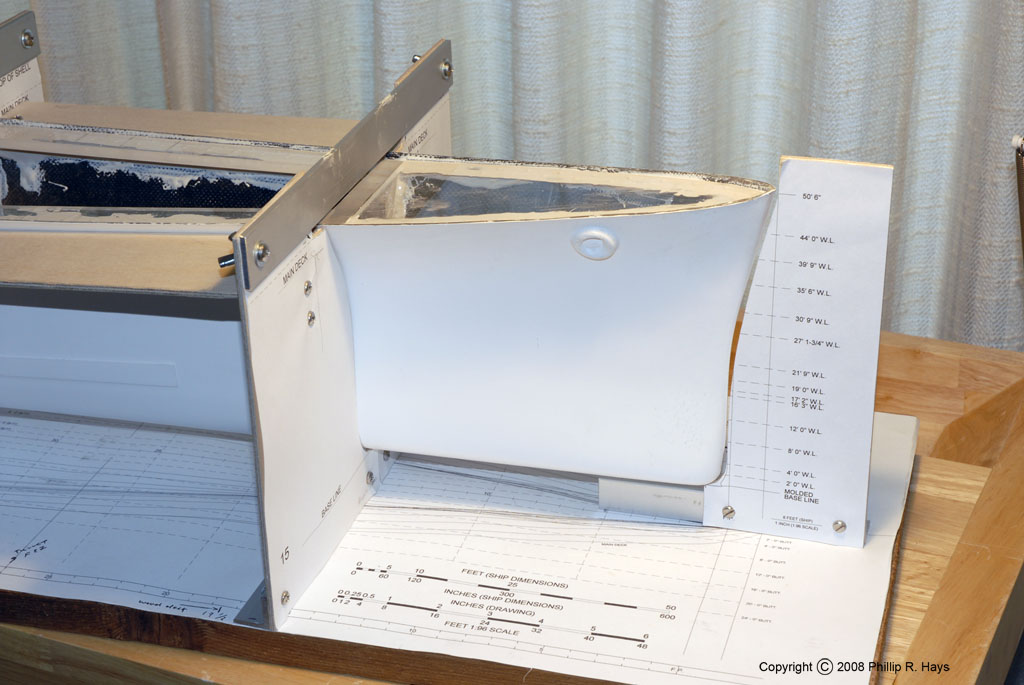
At the bow and stern I placed additional "L" brackets along the centerline of the ship and attached plywood templates to these to mark the profile. Between the transverse frame templates I attached plywood formers that were cut to the shape of the hull at the main deck. These were attached to the frame templates with aluminum "L" brackets and screws. When all of these pieces were screwed together around the hull the fiberglass sides were held in position firmly. This ensured that the hull would maintain the proper shape as the structural pieces were fitted into it. This frame was also intended to help with the installation of the propeller shafts to ensure they were positioned correctly in the hull.
Framing the Hull
The first step in building the model was to create seven transverse frames to fit into the hull to give it rigidity. This was actually an arbitrary number - it just looked like that would be enough to support the deck. These were placed at frames 15, 35, 55, 75, 95, 115 and 137, matching the positions of the plywood templates in the hull shaping frame. Fortune has it that my business is next door to a plastics machining company and they toss out all sorts of scraps into their dumpster. I asked and they said they didn't mind if I took whatever I needed, so much of the frame materials were procured by dumpster diving. They just happened to be tossing out a lot of 1/2" plexiglass sheet scraps that were large enough for 1:96 cruiser frames. I used a milling machine to cut the frames from the plexiglass sheet.

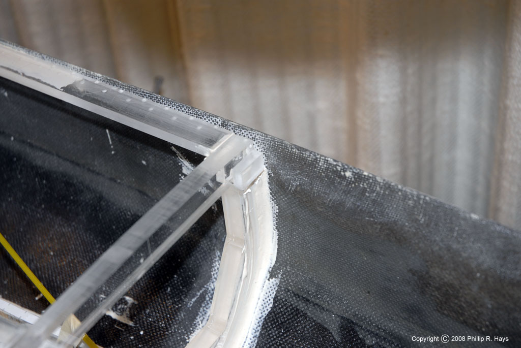
All surfaces were sanded to create a rough surface for the glue to adhere to. Everything was cleaned with acetone, then with water and dishwasher detergent, and then they were thoroughly rinsed to remove the soap. This procedure removed oils and water soluble contaminants. Absolute cleanliness is necessary to get a good glue bond. A long strip of 1" x 1/4" plexiglass was glued in place inside the hull along the keel from frame 21 to frame 115. I used "SuperMend Epoxy Paste" to glue the plexiglass to the fiberglass. I have had good luck with this product and it cleans up easily with rubbing alcohol. The hull frames were notched to fit over this inner keel - this prevents them from moving out of alignment while the glue is setting. I used a 1/16" drill to cut shallow "dimples" into the plexiglass on the surfaces to be glued. Then the frames were glued in place, using clamps to hold them in position inside the hull. When applying the epoxy I first flowed the glue into the dimples and then filled out the joints. After the epoxy hardens the dimples give extra strength to the joints. You can see these dimples in the photographs. I used a lot of epoxy! The hull was clamped tightly between the frames and the wooden templates until the epoxy cured.
The next step was to fabricate the longitudinals that fit along the sides of the hull between the frames at the main deck line. These were 1" x 1/4" plexiglass strips that were cut along one edge to match the curve of the hull at the main deck and trimmed for a slip fit between the hull frames. These were positioned so the top sides of the 1/8" plexiglass deck pieces would be at the correct main deck level. The edges were filed with a rasp to shape them to fit flush with the inside of the hull at the deck line and then the edges and lower surfaces were dimpled. The photos show how the pieces fit together. I glued small plexiglass blocks to the frames to provide support for the longitudinals. The plexiglass parts were glued together with Weld-on 4 Acrylic solvent cement. This thin solvent flows between smooth surfaces and melts the plastic together to form a very strong bond. I roughed the surfaces with sandpaper, cleaned them, and then coated the joining surfaces with epoxy, making sure to fill the dimples without trapping air bubbles. The longitudinal deck supports were slipped into place between the frames and additional epoxy was applied to fill cracks and form a thick bead between the plexiglass and fiberglass hull. The hull sides were clamped tightly between the longitudinal deck supports and the plywood templates of the hull frame. This ensured that the hull had the correct shape at the main deck level. After the clamps were in place I flowed some Weld-on 4 solvent between the ends of the longitudinals, the frames and the plexiglass support blocks. For the bow and stern I cut 1/4" thick plexiglass pieces to serve as supports for the main deck and to create the form to shape the hull sides to the proper curvature. These were prepared and glued into place like the longitudinal deck supports. They are visible in the bow and stern hull shaping frame pictures shown above.
Each of the pieces was glued into position separately, and the epoxy was allowed to harden before work started on the next piece. The epoxy is fairly quick setting and starts to thicken in about 10 minutes. It is quite hard after 30 minutes, and can be sanded after 4 hours, but doesn't fully cure for about a day. After all the pieces were installed the hull was very rigid.
A word of caution is necessary concerning the use of plastics for large scale model construction. All plastics expand when they get warm - much faster than wood or metals like aluminum. You must take this into account if you use large pieces of plastic of any type for decks or internal structure. Acrylic (Plexiglas) has a thermal coefficient of expansion of 3.8 in/in/°F x 10-5 (6.0 cm/cm/°C x 10-5). This means that a 6 foot (1.83 meter) piece of acrylic will lengthen by 0.0027 inches (0.069 mm) for every degree of temperature change. In direct sunlight the deck and superstructure will heat up faster than the water-cooled hull, especially if decks are painted dark deck gray. If the deck is 20°F (11.1°C) warmer than the hull (very possible on sunny days) it will expand by 0.055 inches (1.4 mm)! Other plastics can expand nearly twice as much, while fiberglass (glass reinforced polyester) expands only a little more than 1/3 as much as acrylic. Wood expands even less. Because of this characteristic large plastic decks will buckle when heated if they are fastened securely at the ends.
I learned this the hard way. After building up the hull with Bondo (see below) I left it outside to cure in direct sunlight. All of the Plexiglas frame members heated up and expanded. Since they were a tight fit along the entire length of the hull, and caged inside the fiberglass hull, they couldn't expand freely as the temperature rose. On one side an internal longitudinal framing piece at the main deck level popped out of place. Apparently the heat had weakened the epoxy so the part pulled free. I had to cut away the old epoxy and clean up all the parts, then glue the piece in place again. I will need to cut expansion joints through the longitudinals, and leave gaps in the 1/8" thick acrylic deck to prevent future temperature related problems.
Hull Modifications
The first time I placed the hull in the Hull Shaping Frame I noticed that it did not fit correctly at the very bottom along the keel. At first I thought the frame might not be correct, but the drawings I used to build the frame were based directly upon the original blueprints. I eventually decided that the hull was slightly hogged and the aft end of the keel was not deep enough. Maybe this wouldn't matter with a radio controlled model, but it was unacceptable for a display model. I decided I would have to correct the problem.
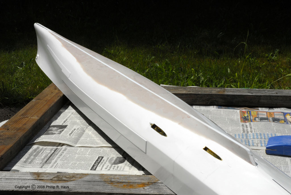
At the aft end of the keel the hull was 1/4" too shallow - two scale feet. The bow was OK, but in between the keel was not straight along the ship's base line. To correct this I glued a 1/4" square styrene strip to the keel. Then I carefully shaved this strip to produce a flat surface from the bow back to the end of the keel. Next I built up the hull surface with Bondo, using the Hull Shaping Frame templates as guides. After several layers and a lot of sanding I had a hull that was the correct shape.
Rudder
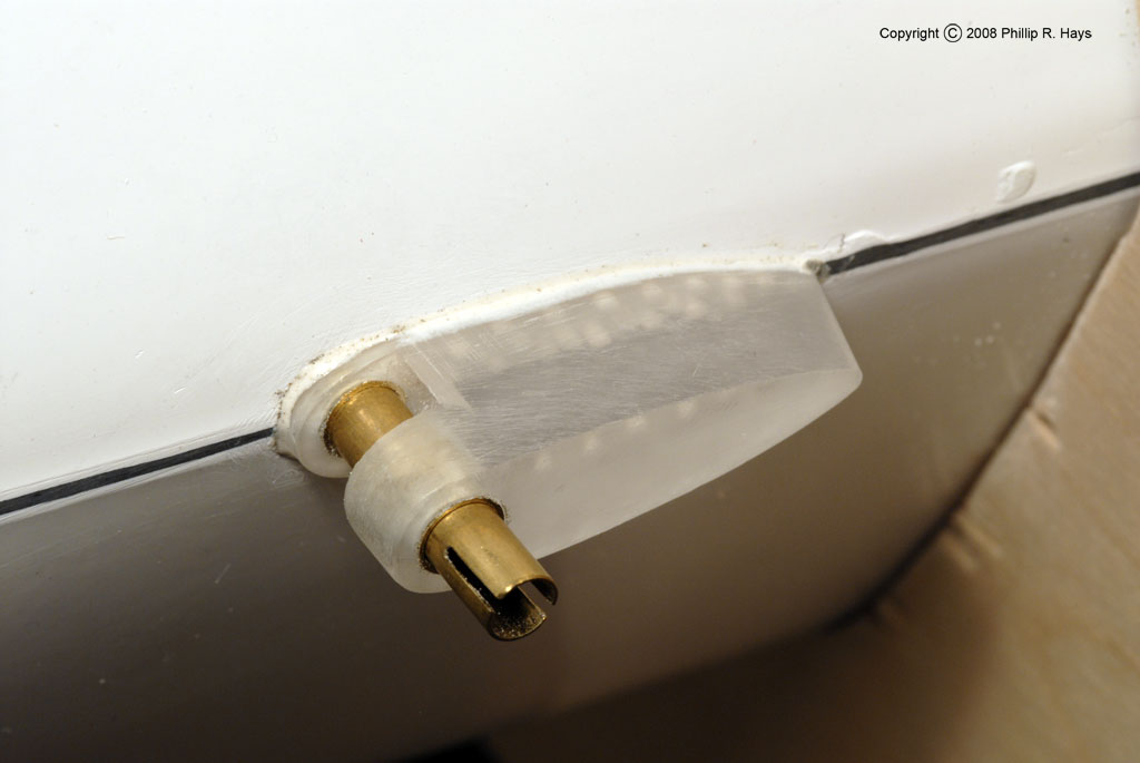
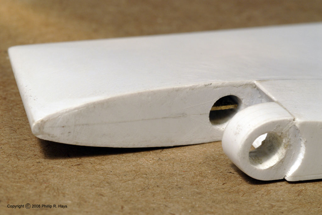
I fabricated a rudder from styrene sheet, using the original blueprints as my guide. I wanted the rudder to function because I wasn't sure if I wanted to make a radio controlled model or just a static display (this issue is still being debated). I designed a simple mechanism consisting of a brass bracket attached to the rear frame to support a vertical brass tube that penetrated the hull. The bottom of the tube was epoxied in place and the top was soldered to the support bracket. The top is well above the waterline to prevent water from entering the hull through the tube. The bottom end of the rudder tube extended through the rudder skeg on the outside of the hull. I carved the skeg from plexiglass and epoxied it to the hull. After the epoxy hardened I trimmed the rudder tube, leaving parts embedded in the skeg to serve as bushings for the rudder post.
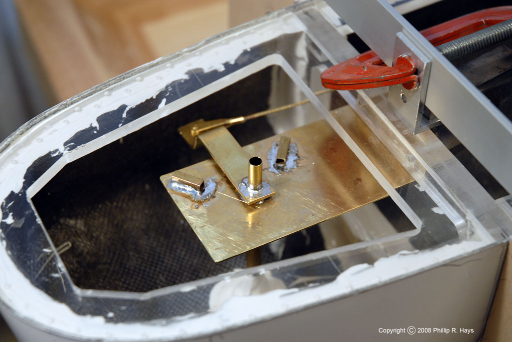
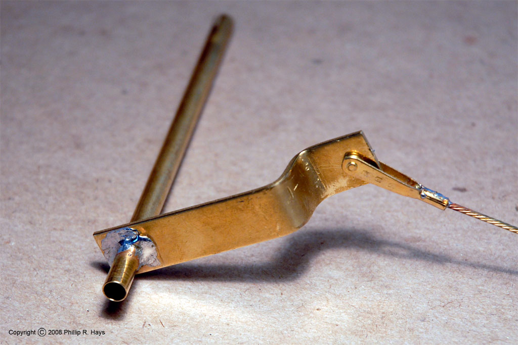
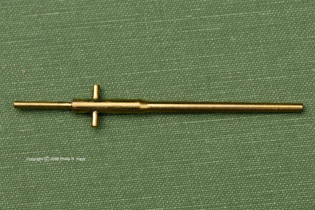
The rudder mechanism caused me a lot of thought. The rudder and skeg fit together like jigsaw puzzle parts. If I installed a rudder post that was attached to the rudder the rudder couldn't be removed. I came up with a scheme that works quite nicely. The rudder post is a brass tube that rotates inside the rudder tube. At the top end is a lever arm with a hole at the end to accept a push wire. The push wire is a common R/C model airplane part. The wire runs forward through a tube along the side of the hull. When the rudder turns two pieces of square brass tubing that are soldered to the rudder bracket limit travel of the lever arm. The bottom end of the rudder post tube passes through the skeg. It is slotted to fit over a thin brass plate built into the rudder. To assemble the mechanism the rudder is fitted into the skeg and the rudder post is slipped into the rudder tube and pushed down until it contacts the metal plate in the rudder. Then the rudder is rotated until the rudder post drops down over the plate. The top of the rudder post sticks up to almost rub against the bottom of the main deck. When the deck is in place the post cannot rise up far enough to allow it to disengage the rudder plate.
Propeller Shaft Alleys
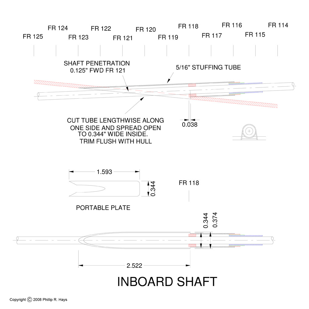
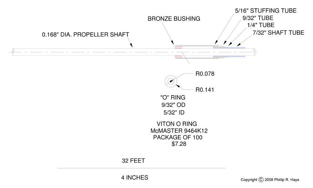
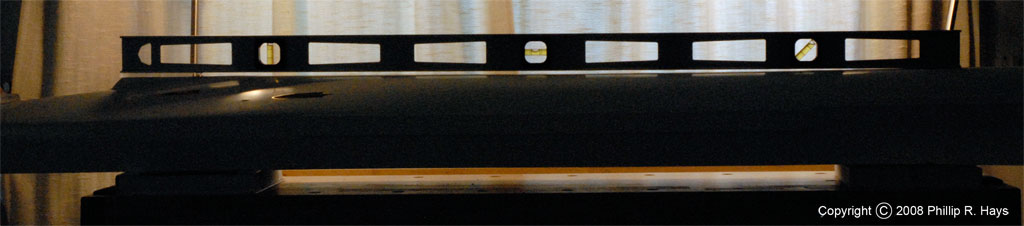
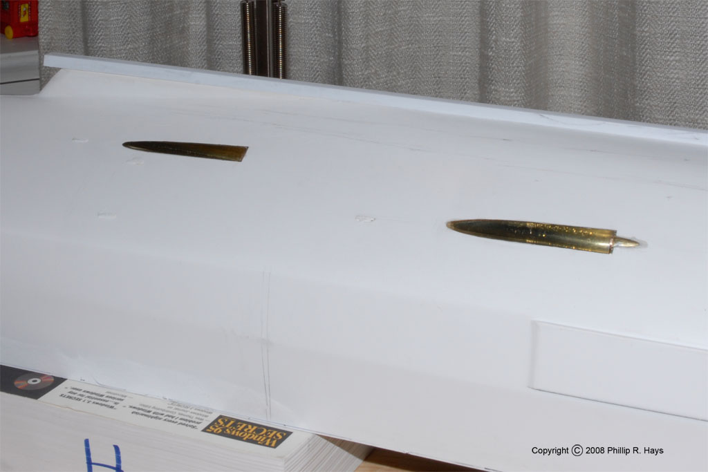
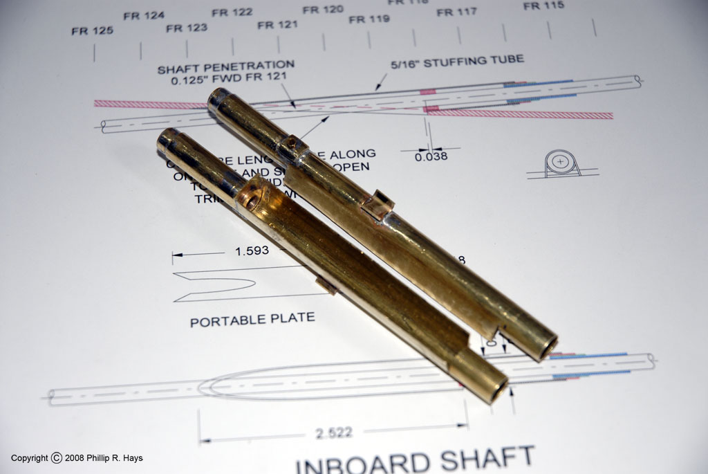
The propeller shafts were fairly long 0.168" diameter (scale 16") drill rods. They fit into 7/32" brass tubes with an internal diameter of 0.188". These propeller tubes fit between the stuffing tubes in the shaft alley hull openings and the motors (assuming there will be any motors). Where the propeller shaft penetrates the hull there is an elaborate cavity that I wanted to model accurately. But I also wanted to build a water tight stuffing tube with a support bearing. After a bit of experimentation I came up with a design that is a scale representation of the real thing, but has a removable oil-bronze bushing, one or more O ring seals, and has features to allow easy alignment and attachment into the hull.
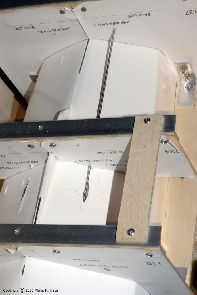
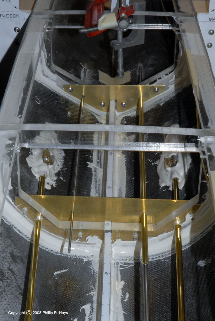
Propeller shaft alignment was a critical part of the assembly. I wanted it to be as close as possible to the real thing. The Hull Shaping Frame was designed to facilitate propeller shaft alignment. The plywood templates were drilled with holes that were a tight fit around some small diameter rods (that will eventually be parts of the radar towers). Each shaft passed through two templates and the point where they contacted the hull marked where I would drill the hull opening. It was reassuring to see that the shafts aligned nicely with the features molded into the hull to mark the propeller shaft openings. I started with a small hole just large enough to allow the shaft to pass into the hull. I also created templates to fit inside the hull to mark where the propeller shafts passed through the frames. Again, two templates were used to allow the shafts to be lined up internally. After these rods were turning freely in all the supports I started enlarging the support holes to allow larger diameter rods to pass, eventually working up to the 7/32" shaft tubes. When these fit snugly into the holes in the hull and the internal support brackets it was time to fit the hull openings to the shaft cavity assemblies.

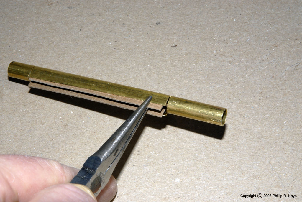
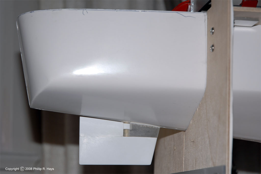
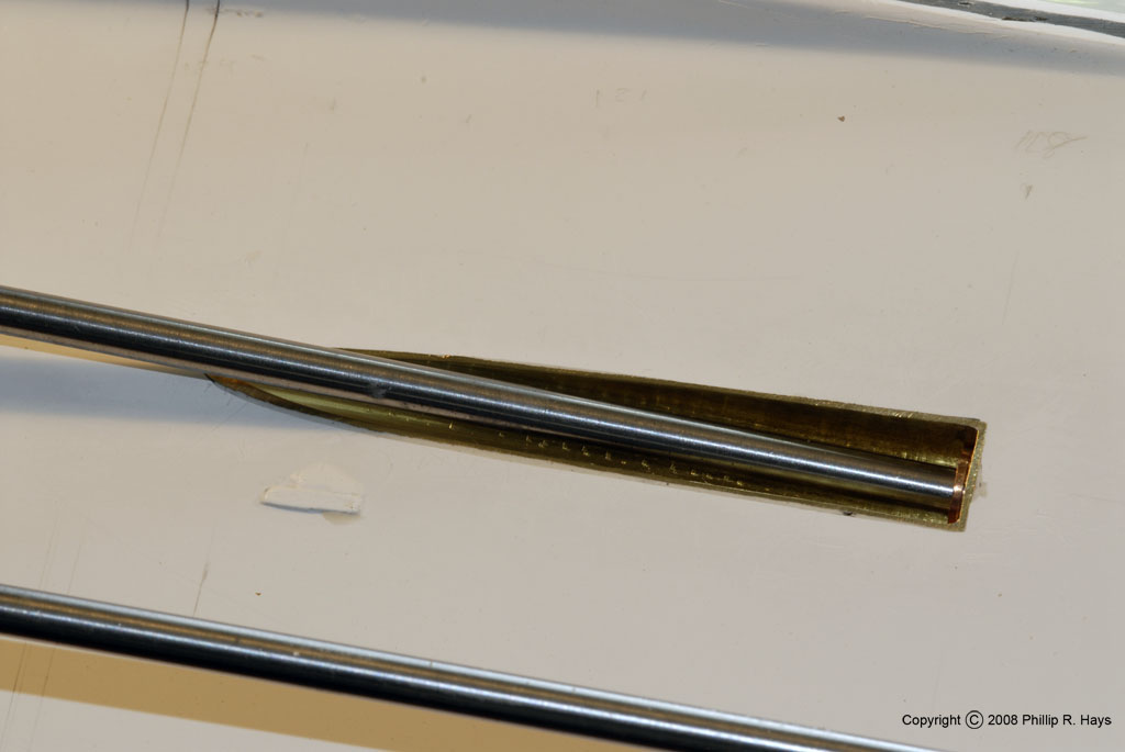
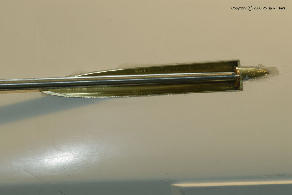
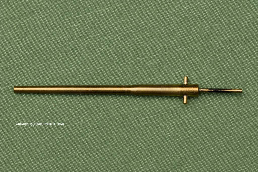
The hull shaft cavities were made from 5/16" brass tubes. The idea was to cut them down one side and open the tubes into a "U" shape. First I cut slots across the tubes and then I worried a lengthwise slot by using the tip of a small saw as a rasp to gouge out metal until the tube wall was penetrated. Then I just sawed the full length of the slot. I used a pair of smooth jawed pliers to spread the tube open, with a piece of cardboard on the inside to protect the finish of the metal. This left one end of the tubes intact to become part of the stuffing tube, and the other end to hold an alignment tool.

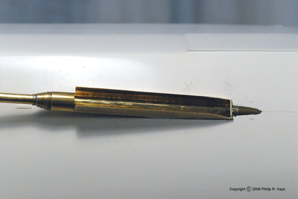
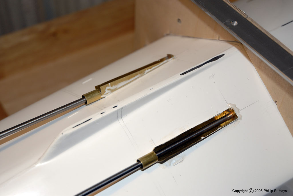
The "U" tubes were fitted over the ends of the propeller tubes with a series of short concentric tubes of decreasing diameter, with each larger tube just fitting over the next smaller tube. These were soldered together to create the stuffing tube. I had to solder two support tabs to the tubes to provide strength and rigidity for the stuffing tubes, and a bulkhead plate to complete the forward end of the cavity. At the other end of the 5/16" outer tube I fitted another assembly of concentric tubes, but this alignment tool was not soldered to the outer tube so it could be used on all four assemblies. This allowed the propeller shaft tube to pass through the stuffing tube assembly. The holes in the hull were enlarged to allow the 5/16" diameter cavity assembly to slide along the propeller tube and just fit tightly into the hull opening. This ensured the cavity was aligned in the correct position and the propeller shaft would turn freely.
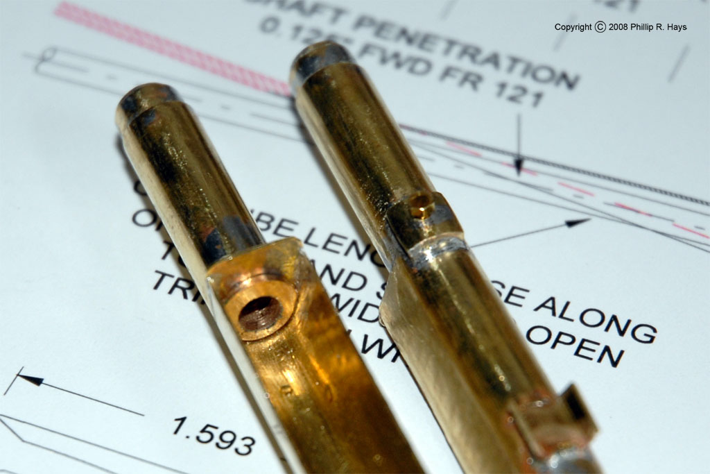
The cavity assembly was completed by fitting an oil-bronze shaft bushing into the opening in the stuffing tube. The bushing was turned from bronze rod and then fitted to the cavity shape. A brass block was soldered to the outside of the stuffing tube opposite the bushing. It was drilled and tapped for a small set screw to hold the bushing in place. The completed shaft tube assemblies had extra brass tabs soldered on to serve as handles for the epoxy cement that would seal the tubes to the hull.
The parts were fitted in place and the propeller shaft was tested to ensure freedom of motion. After everything was cleaned thoroughly lots of epoxy was poured around the fittings to ensure a good water tight seal.
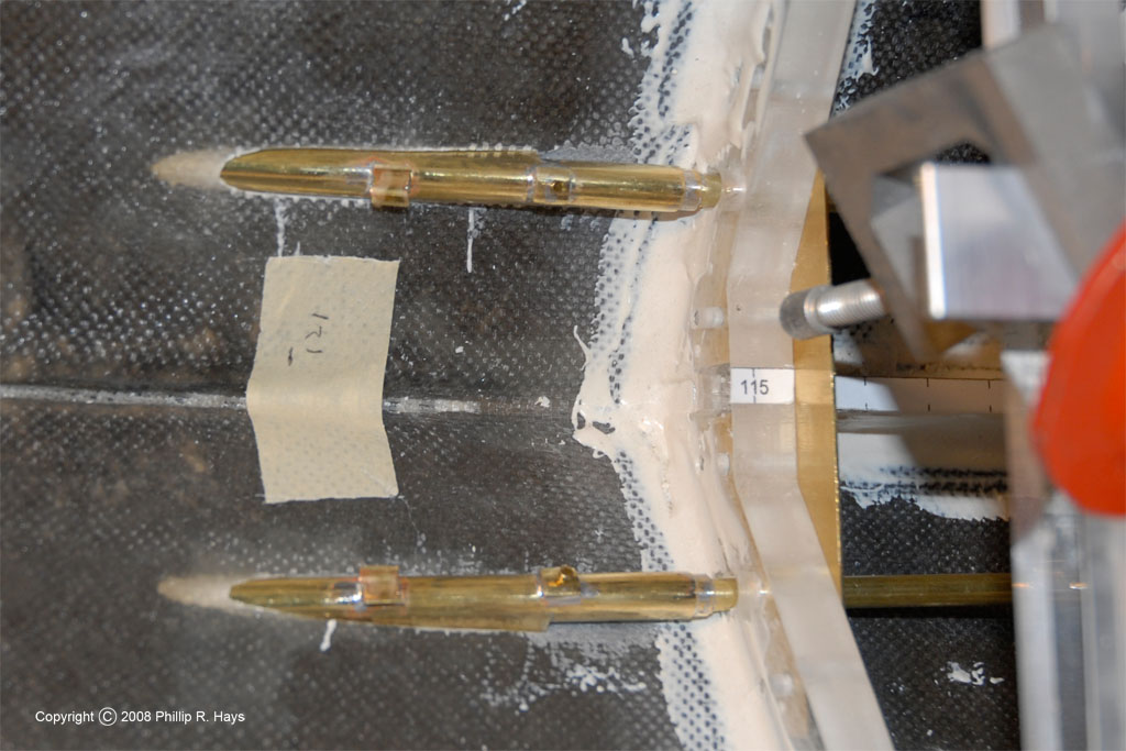

All that remained was to cut away all of the metal extending outside the hull surface. I surrounded the area with several layers of wide masking tape before I started so a slight slip wouldn't damage the hull. I used a thin blade saw to cut the metal to within 1/16 inch of the surface and then I used a series of coarse and fine files to finish the job. The inboard and outboard shaft cavities are slightly different, and all needed a little bit of touch up with epoxy to repair the chipped edges around the holes. After polishing with steel wool and painting the cavities will look as if they were molded into the hull. The final model will have "portable plates" (portable means they can be removed) covering the forward ends of the cavities. These helped streamline water flow on the original ship. Here they will hide the shaft bushings.
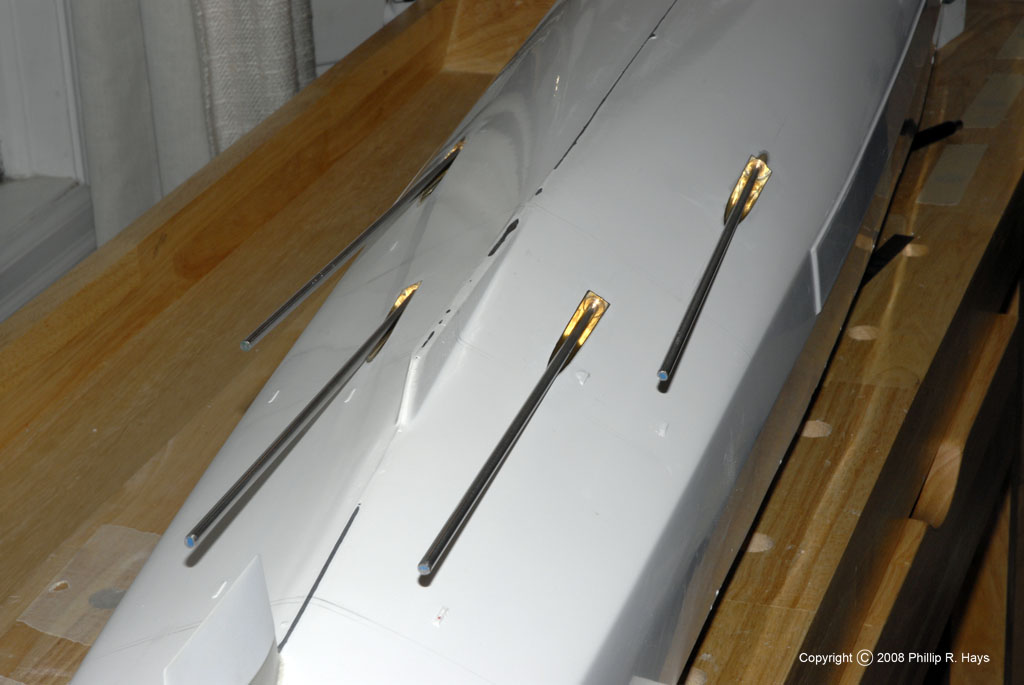
Propeller Shaft Struts
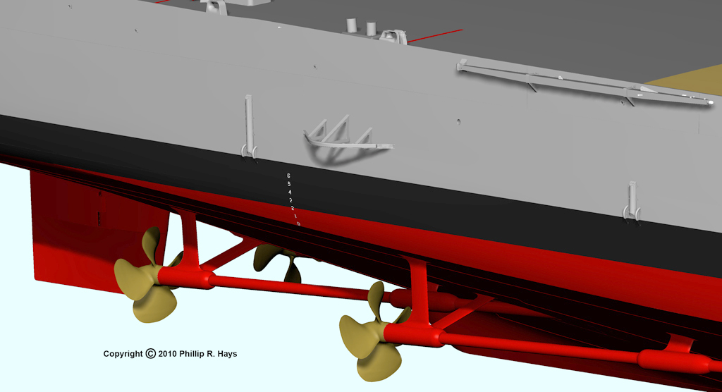
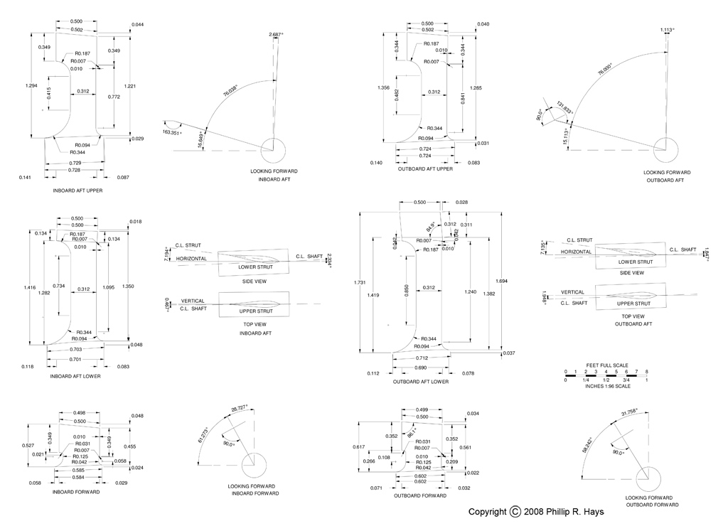
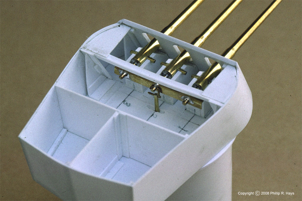
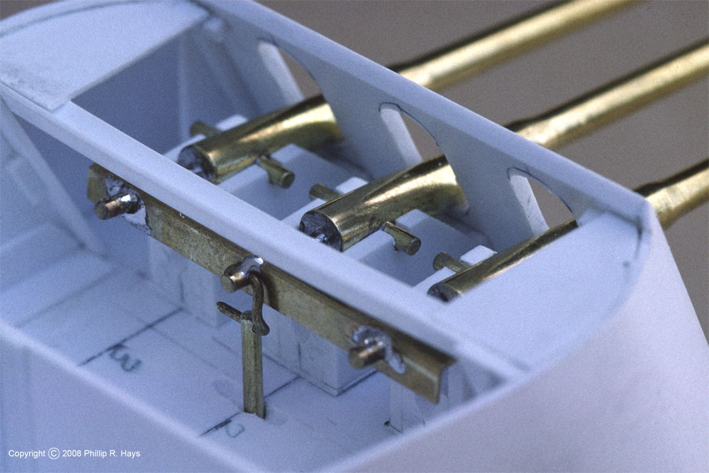
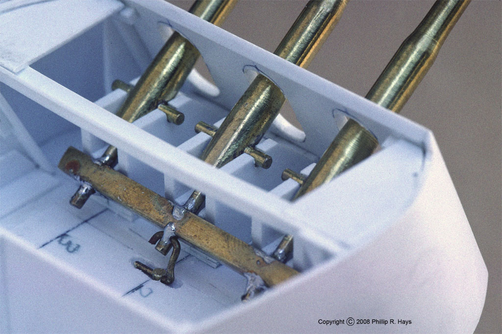
Each propeller shaft had two supporting struts that attached to the hull and kept the shafts in alignment. The shaft passed through bushings in the support tube. The real thing was a single casting about 12 feet across that included the struts and tube. To model these I cut each strut from a sheet of 1/16" brass. Then I used files to shape the strut to the proper "airfoil" cross section shape. The support tube is a piece of 5/16" brass tube with turned oil-bronze bushings in each end to give the correct fairwater shape. The pieces will be assembled in place on the hull, using the propeller shafts as alignment jigs. The struts will pass through slots in the hull and be fastened to an internal "L" bracket. Then a blob of epoxy will form a seal. I will use a solder fillet to fair the surface of the struts into the surface of the tubes.

Turret
I made the turret support frame from 1/4" plexiglass. The transverse frames are glued to the side deck support longitudinals. The plexiglass main deck will be glued to the top edges of the support frame. The barbette is a 2 1/4" (18 foot scale) piece of PVC pipe I bought at my local hobby/plumbing supply store.
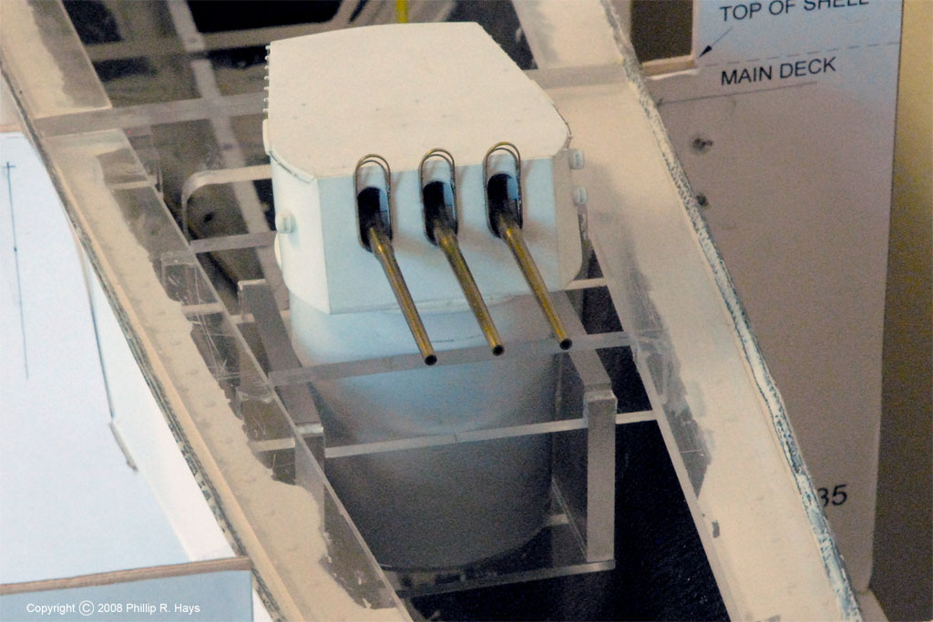
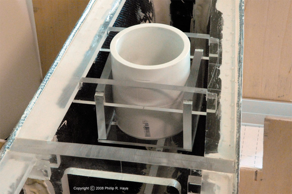
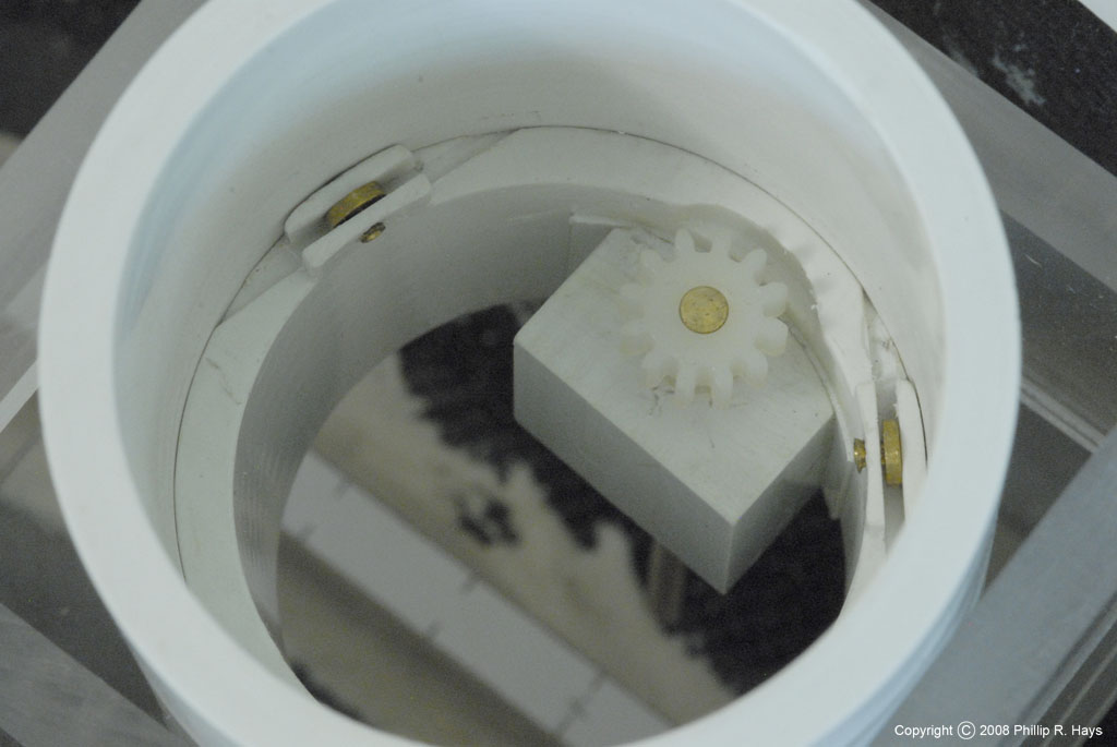
Inside the barbette is another piece of PVC pipe that serves as the turret support. I installed three brass rollers in the support. The turret rides on these rollers. By sliding the support in the barbette I can control the spacing between the turret and the barbette top. I also installed a gear to rotate the turret, in case I decide to add radio control to the model. On the bottom of the turret is a frame and a disk that fits loosely inside the barbette. This disk rides on the rollers in the support frame. A gear will be fastened to the disk to engage the drive gear in the barbette.

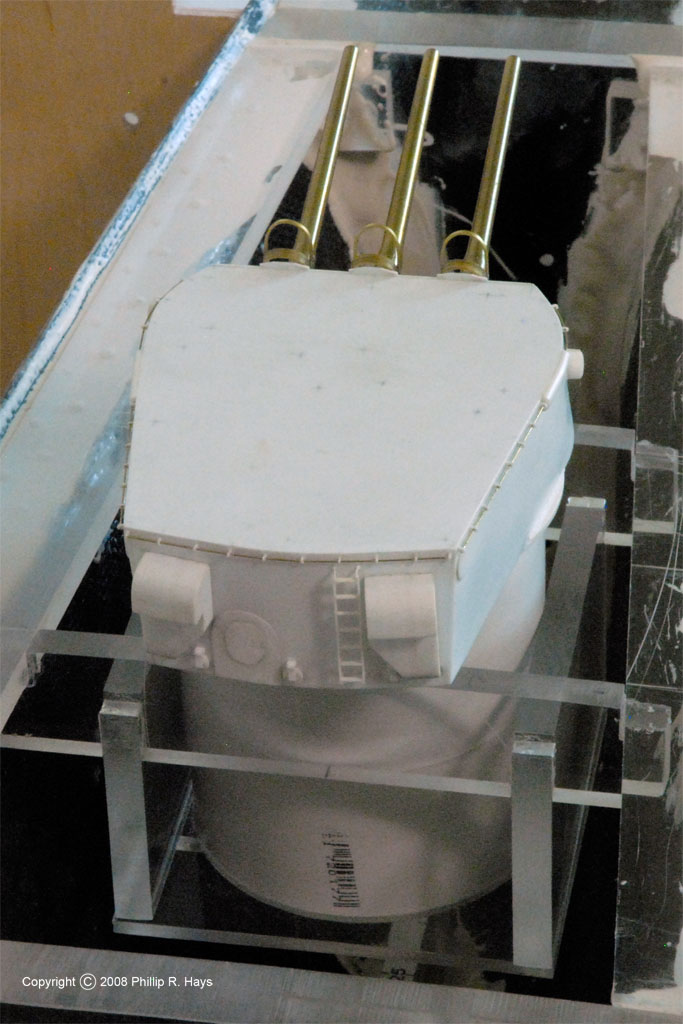
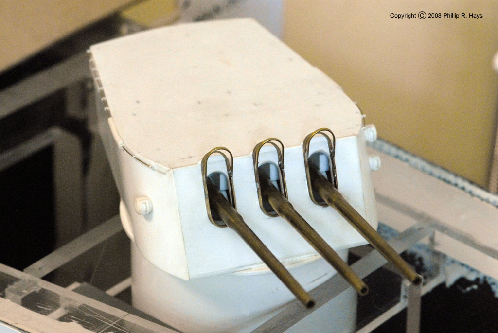
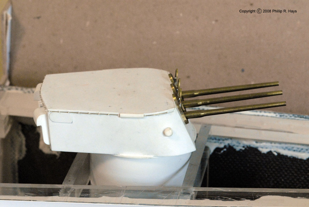
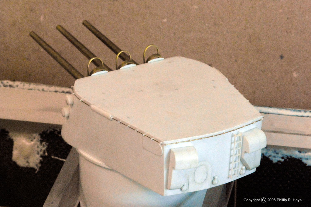
The turret is made from 1/16" styrene sheet. I constructed a support frame for the guns to allow them to elevate. The gun barrels were turned from brass. I soldered a cross member to the breech ends of all the guns so they would elevate together. They pivot on 1/16" brass pinions that are captive in the styrene frame. A brass push rod is attached to the cross member and penetrates the base of the turret. It is part of the gun elevation mechanism.
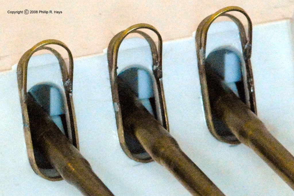
The turret has many fine details. On the front are the bloomer support frames, made of 1/16" and 1/32" flat brass bar. Eventually I will make the bloomers for the guns. I plan to carve plastic molds and then dip them into the liquid rubber stuff used to coat tool handles. Along the sides are 0.010" rods to support canvas awnings when the ship was in port. On the rear is a ladder constructed of 0.025" x 0.010" styrene strips, vents, shell case ejectors and a door frame and door, all made from styrene. On the top you can see a bunch of pencil marks where the top side detail will be added. All of these details will be very fragile, so I will wait until I am ready to paint before adding them. Right now it is convenient to be able to place the turret on its top while I am working on the hull.
Gun Mount
I haven't done much yet on the twin 5"/38 gun mount. The gun barrels were turned from brass. They will be mounted in the same way the 6"/47 guns were mounted. The gun house will be made of 1/16" styrene pretty much like the turret.
Smoke Pipes

The smoke pipes (funnels) carry a great deal of fine details and complex curved shapes. I decided to try to photoetch the detail parts using the Pro-Etch System from Micromark. It worked pretty well for most of the parts but I did not get good results with very fine detail. The process requires a fairly simple photo exposure and fixing for the etch resist film but I found that it does not fix uniformly across the sheet. Consequently, for fine detail pieces like the catwalks, which have 0.010" wide bars spaced with 0.012" gaps (in 0.010" thick brass), I got pieces that were etched correctly in some places but either over etched or under etched just an inch away on the sheet. The problem was an invisible extremely thin layer of resist that remained in exposed areas and prevented etching. However, as you can see in the picture it worked nicely for making the skirts that wrap around the smoke pipes and the complex deck shapes. I still have to figure out how to make the catwalks.
Radar Towers

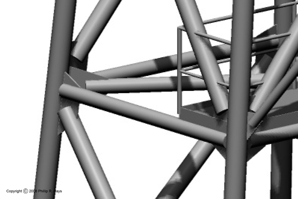
I haven't started on the towers yet. I want to include the gusset plates as well as the tubes, but this means as many as 15 pieces (9 tubes and 6 gusset plates) will have to be soldered together at a single position. Just holding all the pieces in the correct orientations will be a challenge. I plan to use a series of solders of decreasing melting points for subsequent stages of the assembly so the parts that were soldered first won't melt loose as later parts are added. I have no idea if this will work. If you have experience at this and can offer suggestions, any help will be much appreciated!
Problems
Any scratch built project like this will be a series of problems that must be solved before it can be finished. Most of the problems I am facing are all a matter of scale. At 1:96 a scale inch is 0.0104." Much of the original ship was built with 3/8" plate, and that would be 0.0039" at 1:96 scale. Four thousandths of an inch is pretty thin, about the thickness of a sheet of 25# paper. In most cases material thickness doesn't matter because all you will see is the surface, but all of the coamings on the ship should be this thin. These stick up 3" around the edges of decks, or 0.031" in scale. So I need 0.004" x 0.031" coamings around all the superstructure decks. Any attempt to glue this strip in place would look horrible, so it looks like I will have to cover all of the superstructure in 0.004" sheet of some sort just to get scale coamings. Stainless steel would probably be the toughest material. So how do you cut 0.004" material without wrinkling it? Wrinkles would look pretty crummy too.
I have a similar problem around the edges of the main deck. The hull plating extended between 3/4" and 5" above the main deck plating. Inside this was an angled bracket riveted to the hull plating and the main deck. The hull plating varied from 3/8" thickness (0.004" scale) to 7/8" thick (0.009" scale). So I need hull sides 0.010" thick or less, at least along the top edge. My solution here is to plate the hull just like the real ships. The fiberglass hull will just be the inner support for the plating. This is where the CAD model will come in handy, to determine the actual size of the plates.
I finally found readable drawings for the propellers, and I have a good 3D CAD model. I have searched for suitable commercial products, but I haven't found any that are the right diameter (1.375" or 35mm) and the correct shape (proportional pitch blades). I guess I will have to make them. It will be an interesting NC machining or 3D stereolith project.
I have the original blueprints for most of the ship, but I do not have dimensioned drawings for most of the radar antennas, and I don't know where to get most of them. The drawings for the missile system, including the launcher, have finally been released to the National Archives, but there are dozens of volumes and thousands of pages to sift through. Dimensioned drawings of the 5"-38 and 6"47 guns are also hard to find. Without these drawings I have had to make a lot of guesses based upon photographs. For a simple model these will be good enough, but I am trying to produce accurate documentation for the historical record, and guesses aren't good enough for that.
Like I said, I still have a long way to go before this project is finished.
To be continued ...
June 2017 - the CAD model is nearing completion, maybe this year! Then I will start making photoetch and possibly 3D stereolith parts, and resume assembling the model. Hope it doesn't take aother ten years!