
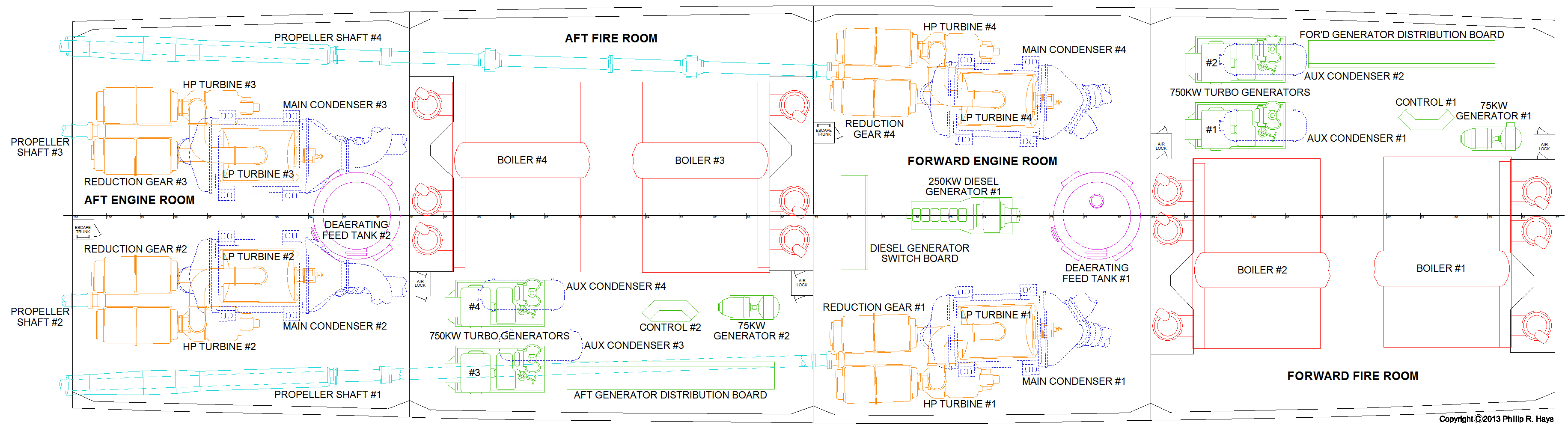
The ship's propulsion plant had a Forward Fire Room, Forward Engine Room, Aft Fire Room and Aft Engine Room. Click on the picture to open a detailed diagram of these spaces. These diagrams are taken from the original Cleveland class plans and show only the major pieces of equipment. There were dozens of pumps, tanks, pipes and other gear jammed into these crowded spaces.
Fire rooms contained the boilers, steam turbine generators and electrical power distribution boards (switch boards). Each fire room had two double furnace boilers. All of the boilers were cross connected so any one boiler could provide steam to any engine or generator. In port one boiler was always lighted to provide steam for the generators and to be ready to get the ship underway quickly. At sea more boilers were lighted and the propulsion plant operated continuously. There were two 750 KW steam turbine generators and one 75 KW motor-generator set in each fire room. The steam powered generators had associated auxiliary condensers to recover the water for reuse. The electrical distribution boards allowed either fire room to supply power to the entire ship.
Engine rooms housed the steam turbines and reduction gears, and the main condensers to recover the boiler water for reuse. They had deaerating feed water tanks to degas the feed water before returning it to the boilers. The forward engine room had a 250 KW diesel emergency generator with a switchboard to distribute electricity to the ship's systems. Space was somewhat limited in the after engine room because of the outboard propeller shafts. A second 250 KW diesel generator was located in a separate compartment aft of the after engine room.
The propulsion system could be operated split-plant where the boilers in the forward fire room provided steam for the generators in the forward fire room and the engines in the forward engine room, and the after fire room provided steam for the after engine room. In this mode the ship had two separate and independent engineering plants. The plants could also be cross-connected where any boiler could provide steam for any engine or turbine. Split-plant operation was normally used when underway because it offered a higher degree of reliability and could continue operations when only one side of the plant was damaged. Cross-connected operation was normally used while in port to allow all generators and steam driven auxiliaries to be powered from a single boiler.
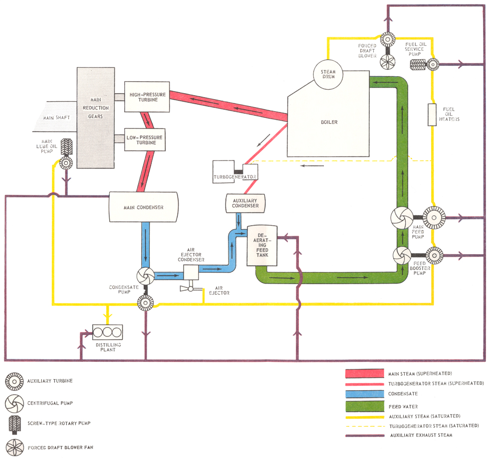
The diagram shows the relationship of the parts of the propulsion system. The boilers produced two types of steam, superheated and saturated. The superheated steam drove the propulsion turbines and the turbogenerators. Saturated auxiliary steam drove turbine pumps and heated the distillation plant. After passing through the turbines the steam was cooled and condensed back into water. Then it was degassed and held in storage until it was pumped back into the boilers. Before entering the boiler the feed water passed through an economizer in the exhaust uptakes from the furnaces to capture some of the heat in the exhaust gasses. Boiler water was very pure, more so than drinking water. Any impurities, especially minerals or salts, would build up in the boiler tubes and eventually cause tube failures.
The engines had two types of turbines, high pressure (HP) and low pressure (LP). The superheated high pressure steam first passed through the HP turbine where it lost energy driving the turbine blades. The cooler and lower pressure steam then passed through the larger LP turbine. The two turbines were designed to capture most of the energy from the steam. They drove the reduction gears which were connected to the propeller shafts. Steam turbines spin much too fast to drive the propellers directly. The reduction gear slowed the rotation to suitable speeds for the propellers while producing a significant mechanical advantage - high speed was converted to high torque. Each engine generated 25,000 horsepower, for a total of 100,000 horsepower to propel the ship.
Boilers
Double Furnace Boiler
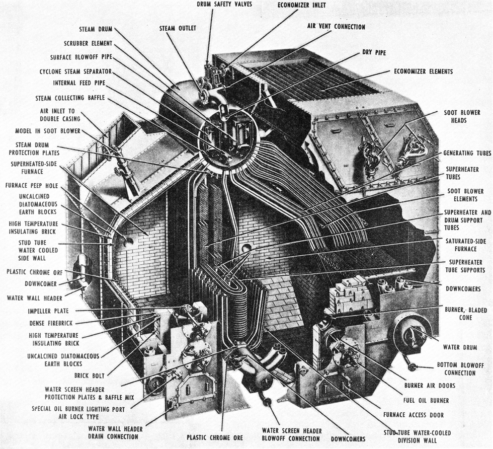
The ship had four Babcock and Wilcox Express Type double furnace (M-type) boilers. These boilers had two furnaces, a first stage saturated steam furnace and a second stage superheated steam furnace. Burners sprayed fuel into the furnaces where it mixed with air and burned to produce hot gasses. These gasses passed through banks of generating tubes filled with water, then through the economizer and out into the uptakes and smoke pipes. The water in the generating tubes absorbed heat from the hot gasses and turned to steam. The steam rose into the steam drum where it collected. From there it could pass through the superheater tubes where it absorbed additional heat.
Each boiler had three steam turbine driven forced draft blowers that drew in outside air and forced it into the boilers at 22,000 cubic feet per minute under 35 inch water pressure (2.5 atmospheres). Air was forced into a pressure chamber on one side of the boiler. From the pressure chamber air flowed between the outer casing and inner casing around the boiler, where it absorbed heat and cooled the outside of the boiler, and then into the burners. The pressure chamber had a double-door air lock to allow personnel to enter the space for servicing while the boiler was operating.
Each furnace had its own set of burners allowing heat in each side to be controlled independently. These were "Iowa-type" burners, nine on the saturated furnace side and seven in the superheated furnace. The number of burners being used was varied according to the need for steam. For normal full power operation only four burners were used in the saturated furnace and four in the superheated furnace. Each burner consumed about 2000 pounds of oil per hour.
When burners were lighted on the saturated side, the water in the generating tubes was heated and saturated steam was produced. When the superheated side burners were lighted (along with the burners on the saturated side), steam flowing through the superheater tubes became superheated. The degree of superheat depended upon the firing rate of the superheated side and the amount of steam flowing through the superheater. The amount of steam depended upon the firing rate of the saturated side. Therefore the amount of superheat was controlled by adjusting the amounts of fuel burned in the saturated side and the superheated side. This arrangement allowed adjusting the amount of superheating to adapt to a wide range of operating conditions.
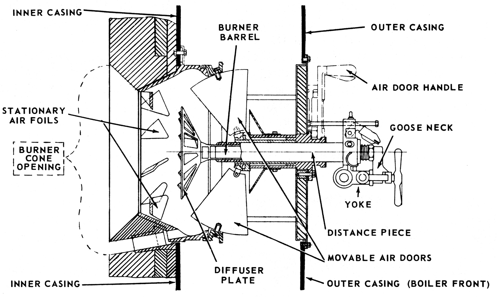
Burners had an atomizer to spray the oil in a fine mist and an air register to control the amount of air entering the boiler and mix it with the fuel mist. Oil was sprayed from the atomizer into a whirling flow of air created by the diffuser plate. Stationary air foils caused additional air entering the boiler to mix with the oil spray beyond the diffuser. The moveable air doors controlled the amount of air that was mixed with the fuel oil.
Steam requirements could change rapidly as the ship maneuvered. The firing rate of the boiler was controlled by changing the number of burners being used and changing the fuel oil pressure. Air pressure was regulated to achieve an optimum fuel-air ratio to ensure good combustion so all of the fuel was burned. The speed of the forced draft blowers was increased or decreased to provide an optimal amount of air for the amount of fuel being burned. At each burner the moveable air doors allowed fine control of the fuel-air ratio to get good burning. Insufficient airflow caused incomplete combustion and produced thick black smoke and "panting" or "huffing" which rattled the sides of the boilers. Too much air reduced combustion efficiency and wasted energy. It was very important to maintain optimum combustion efficiency in order to maximize the ship's cruising range between refuelings.
The ship originally used Navy Special Fuel Oil (NSFO, number 5 fuel oil, or bunker fuel) in the boilers, and was converted to use Navy Special Distillate Fuel (NSDF) in 1974. NSFO is a very thick liquid that has to be heated to get it to flow quickly. Fuel tanks contained steam pipes to heat the oil. NSDF was less viscous and did not require heating.
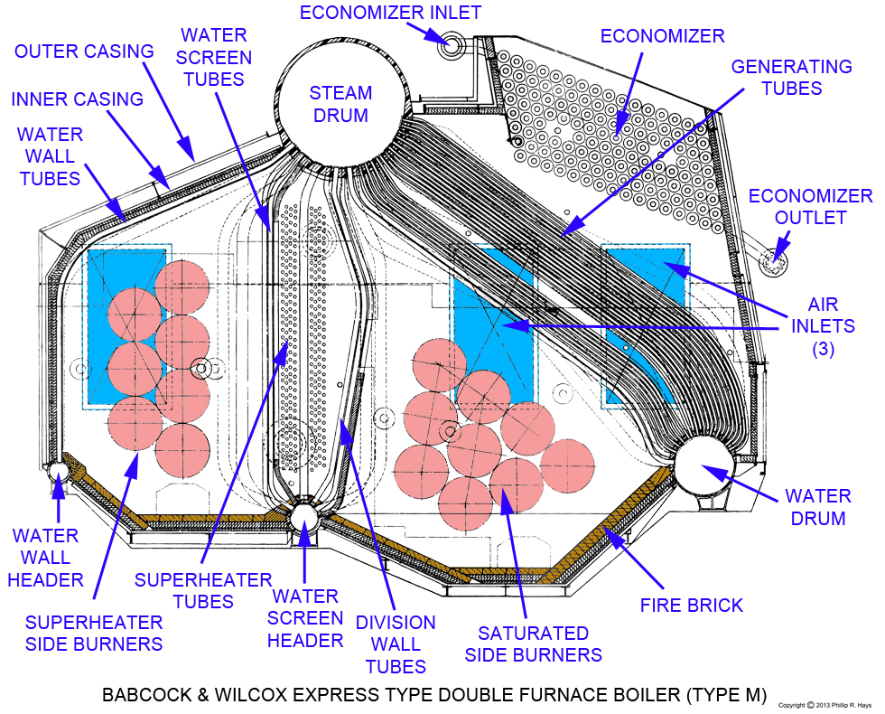
Water first entered the boiler through the economizer, a set of tubes placed in the furnace exhaust outlet to the uptakes and smoke pipes. Here the cool water first absorbed heat from the exhaust gasses and was heated to 250°F to 350°F. From there it flowed to the steam drum. The boiler was filled with water up to about half way in the steam drum. Hot water and steam rose by gravity feed (natural circulation) to the steam drum. Saturated steam at about 490°F and at a pressure of 565 to 615 psi was piped from the steam drum to power pumps, blowers, distillation plants and fuel oil heaters. Saturated steam contains water vapor that lubricates the equipment.
Saturated steam flowed from the steam drum through the superheater tubes where it was further heated to 850°F. Since there was no water in the superheater tubes the steam absorbed heat and became superheated with little or no increase in pressure. This superheated Main Steam was used to power the engines and the turbogenerators. Superheated steam contained more energy than saturated steam at the same pressure. The higher temperature increased the efficiency of the propulsion system due to the greater temperature between the boiler (source) and condenser (receiver). This gave greater range for a given amount of fuel. The superheated steam was free of moisture and caused very little corrosion in the turbines.
Water also flowed into division wall tubes on the saturated furnace side and into water screen tubes on the superheated furnace side. These tubes protected the superheater tubes from radiant heat from the furnace fires. Baffles between these tubes on the superheated side directed the hot gasses over the superheater tubes and away from the steam drum. Baffles between the division wall tubes directed the superheated side furnace gasses away from the saturated side burners, and the saturated side furnace gasses away from the superheater tubes so the boiler could be operated without superheat. The water filled tubes served to cool the baffles so they wouldn't melt. Steam from these tubes collected in the steam drum and cooler water collected in the water screen header.
The walls of the boiler were protected by water wall tubes that absorbed heat from the furnaces before it could get to the furnace walls. Steam from these tubes collected in the steam drum and cooler water collected in the water wall header. Outside the water wall tubes was a 3 1/2 inch insulating layer of diatomaceous earth bricks. Sides and bottoms of furnaces that did not have water wall tubes were protected with a 4 1/2 inch thick inner layer of dense fire bricks.
Additional large diameter "downcomer" pipes connected the steam drum to the water drum (the water reservoir for the boiler), Water wall header and water screen header to provide water to the headers and the water drum. These pipes were routed between the inner casing and outer casing where they were not exposed to the heat of the furnaces. The large downcomers allowed quick flow of water from the steam drum to the lower water reservoirs, providing ample water supply to the heated tubes. Circulation from the steam drum through the downcomers to the headers and water drum then back up the tubes to the steam drum took only a few seconds.
The headers and water drum had outlets to allow "bottom blows" to flush water and debris from the system. The steam drum had pressure relief valves to ensure that pressure didn't rise too high, and it had an outlet for a "top blow" to flush gasses from the drum. Saturated steam was used in soot blowers in the economizer, uptakes and smoke pipes to prevent buildup of flammable soot. Saturated steam was also piped to sea chests (where water passed through the hull) to flush marine organisms and debris from these openings. Steam was also used in heaters throughout the ship.
Each boiler weighed 157,850 pounds dry weight. It held 17,810 pounds water, giving a total wet weight of 175,660 pounds. The boilers had 7471 sq. ft. of heat generating surface, in 1820 saturated generating tubes, 224 superheater tubes, 66 water wall tubes, and 62 economizer tubes. Furnace volume was 1158 cu. ft. with 430 sq. ft. of refractory surface (firebrick and diatomaceous earth blocks). The boilers measured 23' 5" wide, 18' 1" high, and 16' 3 5/8" deep.
Propulsion Turbines
Turbines and Reduction Gear
The engines of the ship consisted of steam turbines and reduction gears. The turbines converted energy in superheated Main Steam into high speed rotation of the turbine shafts. The reduction gears slowed the rotation to speeds appropriate for the ship's propellers. Steam flowed first into the high pressure (HP) turbines where it lost some energy. From there it was piped to the larger low pressure (LP) turbines where it lost more energy. After passing through the LP turbines the steam flowed into the Main Condensers where it was cooled and converted back into water.
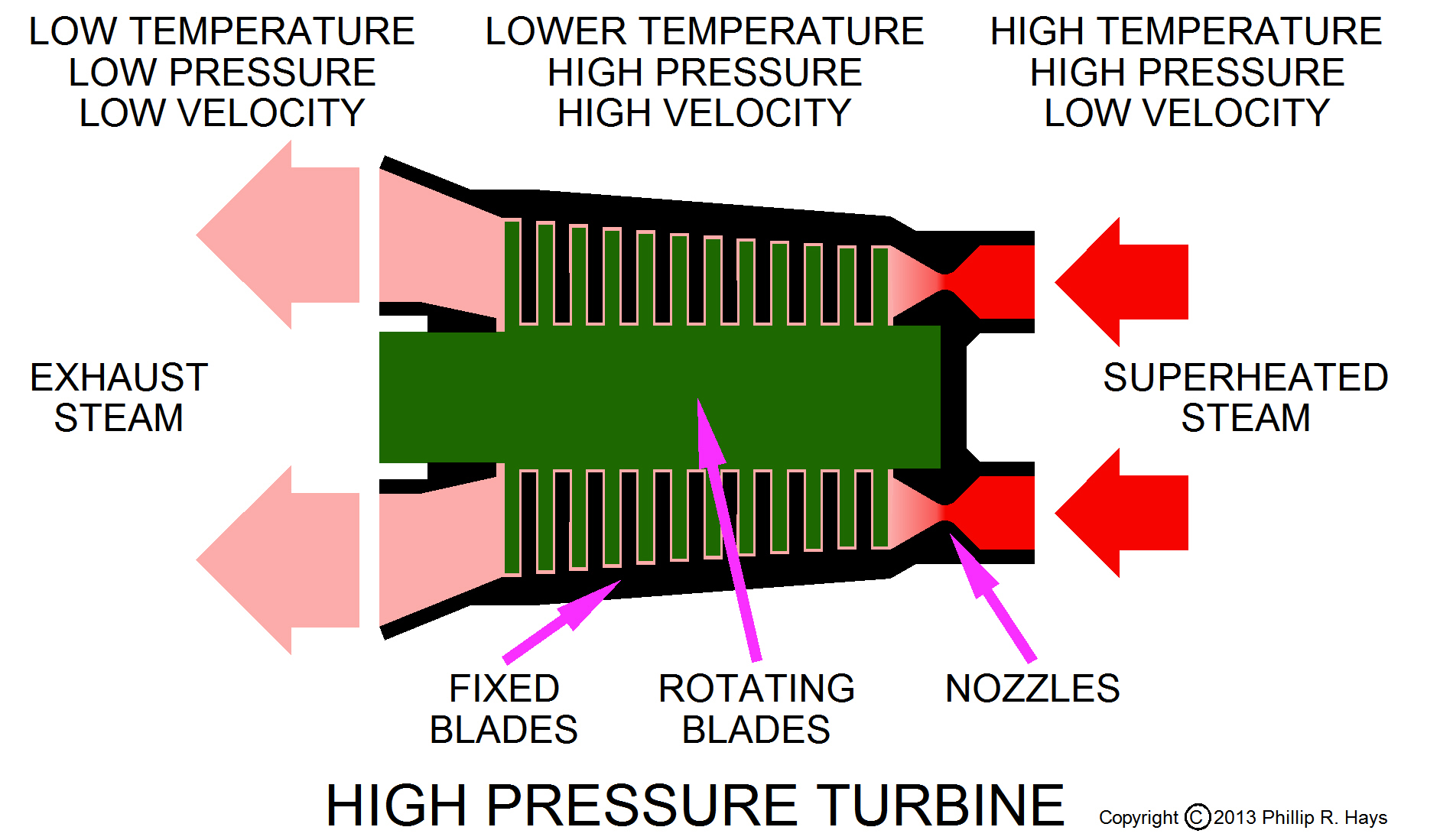
Turbines consist of a rotor, a shaft or axle with a lot of blades attached to the shaft, enclosed in a case that is designed to direct steam flow over the rotor blades. Steam is directed onto the blades through nozzles and causes the turbine to rotate. To increase efficiency several rows of blades are attached to the rotating shaft. This is necessary because one row of blades cannot capture all of the energy in the steam. By providing many rows of blades the total pressure drop is divided into small enough increments at each row that the rotating blades can operate efficiently. The rotating blades increase in size from the inlet side to the outlet side because the steam loses energy as it passes by each blade, and larger blades are needed to receive more energy from the steam. Between these rows of rotating blades are additional rows of fixed, non-rotating blades. The fixed blades serve to redirect steam passing through one row of rotating blades onto the next row of rotating blades. The shape of the rotating and fixed blades is designed to create a nozzle-like effect to accelerate the steam as it passes between the blades, increasing the energy delivered to the next set of rotating blades.
Transfer of energy from the steam into rotary motion occurs in three steps. First the hot steam passes through nozzles that direct the steam onto the turbine blades. As the steam escapes from the nozzles it expands rapidly and cools - the thermal energy of the heat in the steam is transformed into mechanical kinetic energy. The expanding steam rushes at high speed into the turbine blades generating a push or "impulse" as it collides with the blades. The second energy transfer occurs when the high speed steam changes direction as it flows over the turbine blades, producing a reactive force causing them to move. The third force is the reactive force generated on the blades as the steam expands while passing between the blades. The blades are connected to the turbine shaft and cause it to rotate. In this way heat and pressure are transformed into motion.
High Pressure Turbine
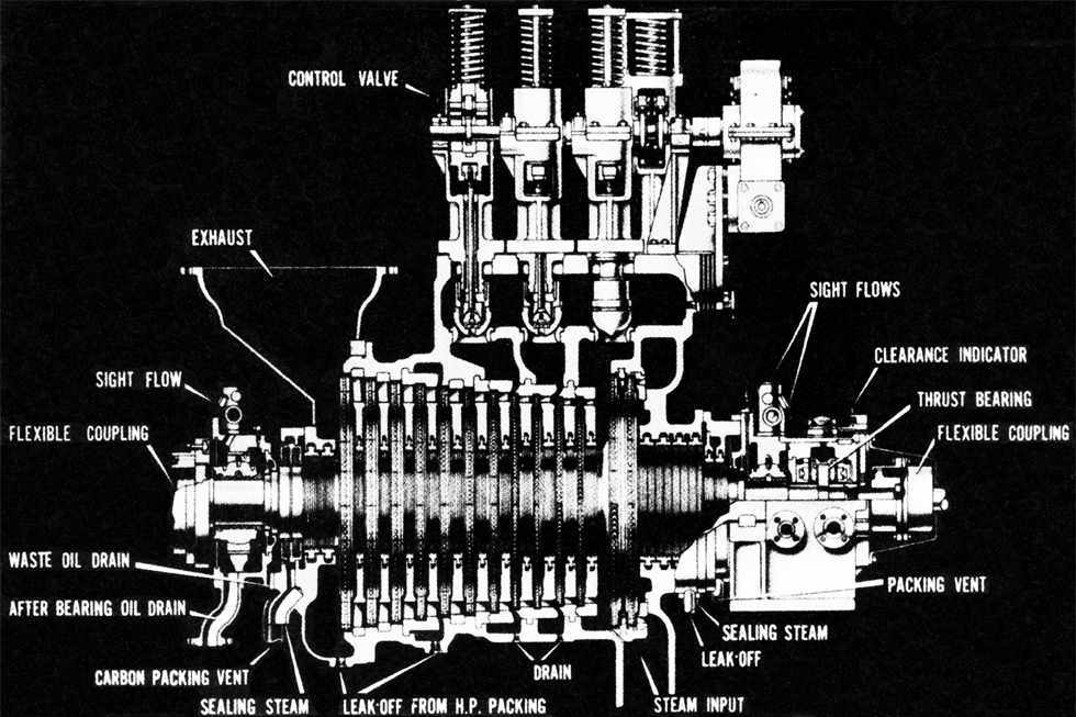
The high pressure turbines were relatively small because not as many blades were needed to capture the energy in the superheated steam. It was a single-flow turbine where the steam entered one end and exited the other. This produced axial thrust along the axis of the rotor, requiring a thrust bearing at the end to absorb the thrust. The turbine illustrated had an initial larger diameter rotor with two sets of blades to receive energy from the superheated steam. These blades formed a "velocity compounded impulse turbine" first stage to absorb the energy from the high velocity steam leaving the nozzles. Following this was a set of moving blades with intermediate fixed blades in a "pressure compounded reaction turbine" configuration. At each blade there was a pressure drop as energy was absorbed from the steam. Each successive blade was larger than the preceding blade to allow it to absorb an equal amount of energy from the lower pressure steam. The entire turbine was a combination impulse and reaction turbine. Steam entered the high pressure turbine at 825°F and 525 pounds per square inch pressure and exited at 425°F and 45 pounds per square inch.
Turbine speed was controlled by increasing or decreasing the number of nozzles in use, thereby varying the amount of steam entering the turbine. Steam was delivered to each set of nozzles through control valves that could be opened and closed in sequence to adjust turbine speed. These valves controlled the amount of steam flowing through both the HP and LP turbines, so the speeds of both turbines were controlled together. At full power the HP turbine rotated at 5,882 RPM and delivered 11,550 SHP (Shaft Horse Power).
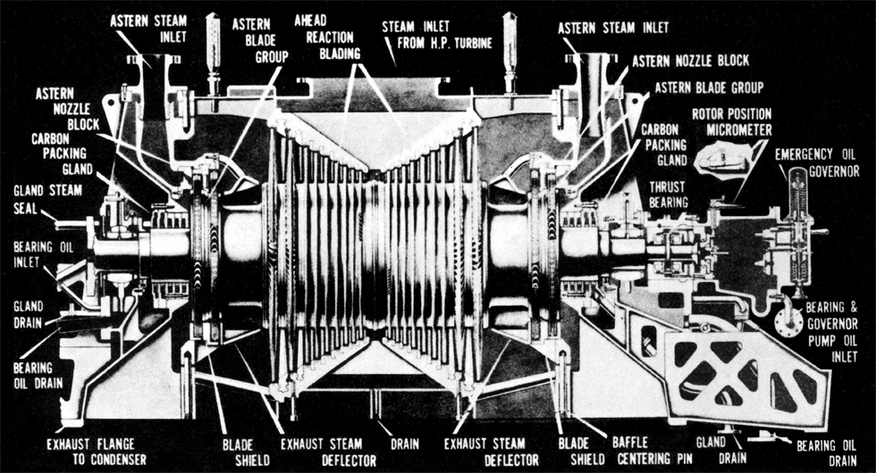
Low Pressure Turbine
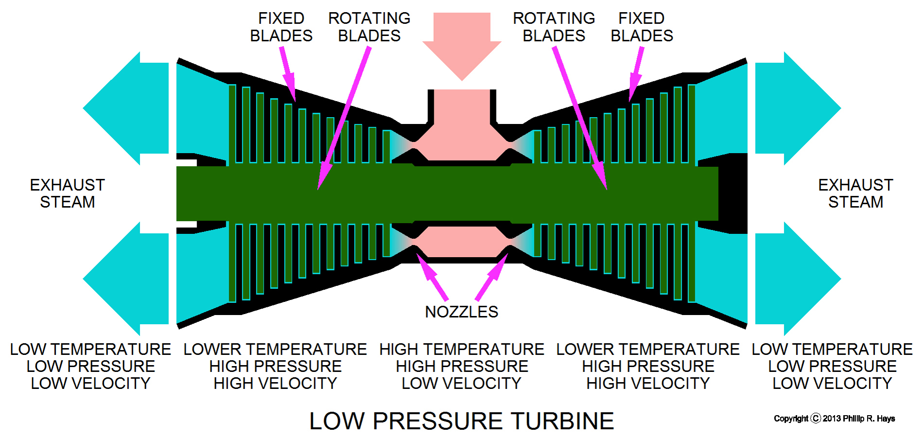
Low pressure turbines were much larger than the HP Turbines. Steam entering these turbines carried lower energy so more blades, and larger blades, were needed. Low pressure turbines were pressure compounded reaction turbines. They were double-flow turbines with steam entering at the center between two sets of blades and flowing out both ends. This arrangement has the advantage that the blades do not have to be as large as they would with a single-flow arrangement. In addition, the axial thrust is equal but opposite in the two sets of blades, resulting in little or no axial thrust for the assembly. At full power the LP turbine rotated at 4,705 RPM and delivered 13,450 SHP.
The LP Turbines had additional blades and steam inlets to produce reverse rotation when the ship must slow down quickly or move backwards. The astern element produced 7000 SHP and rotated at 3225 RPM maximum, using the main steam at 825°F and 525 pounds per square inch. It took about 30 to 40 seconds to change propeller shaft rotation from full ahead (350 RPM) to full astern (218 RPM) in the Builder's Dock Trails with the ship stationary at the pier.
In port the propulsion turbines were idle and cold. When the ship got underway the steam flowing in the turbines heated the assembly, causing it to expand. The amount of expansion could be significant in large turbines, and it exerted a considerable force. This force must not be transferred to the reduction gears or it would cause serious damage. Consequently, the after end of the turbines were securely mounted to the frame of the ship and the forward end was mounted in such a way that it could move as the unit expanded and contracted.
In addition to the parts already mentioned, turbines had bearings to support the rotor shaft, lubricating systems to keep the bearings lubricated, and shaft glands to prevent steam from leaking out and air leaking in at the bearings.
There was also a motor-driven turning gear (jacking gear) that was used to turn the rotor while the turbine was warming up or cooling down to ensure the rotor heated and cooled evenly. If the rotor was not moving while it changed temperature it would bend and drag on the non-rotating parts. The turning gear was also used to rotate the turbine and reduction gears for inspections. It contained a brake to lock the shaft in position. The turning gear was installed on the end of the reduction gear casing.
Some ships had a third type of turbine, a cruising turbine designed to operate economically at lower speeds. Ships normally operate at speeds much lower than their maximum speed to get the most economical use of fuel. The first two Cleveland class cruisers, USS Cleveland and USS Columbia, had cruising turbines. The remaining ships of the class did not have cruising turbines because it was thought that in wartime they would always be moving at higher speeds while escorting fast attack aircraft carrier task forces. Consequently, the USS Oklahoma City did not have cruising turbines.
Condensers
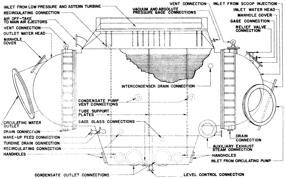
The Main Condensers were heat exchangers where the hot exhaust steam from the low pressure turbines was condensed into water. The condenser contained an array of tubes through which cool sea water flowed. Steam from the turbines flowed around these tubes and lost heat to the sea water. When the steam condensed into water the volume was reduced significantly, creating a vacuum. The condensate collected in wells at the bottom of the condensers and was then returned to the boilers.
Main Condenser
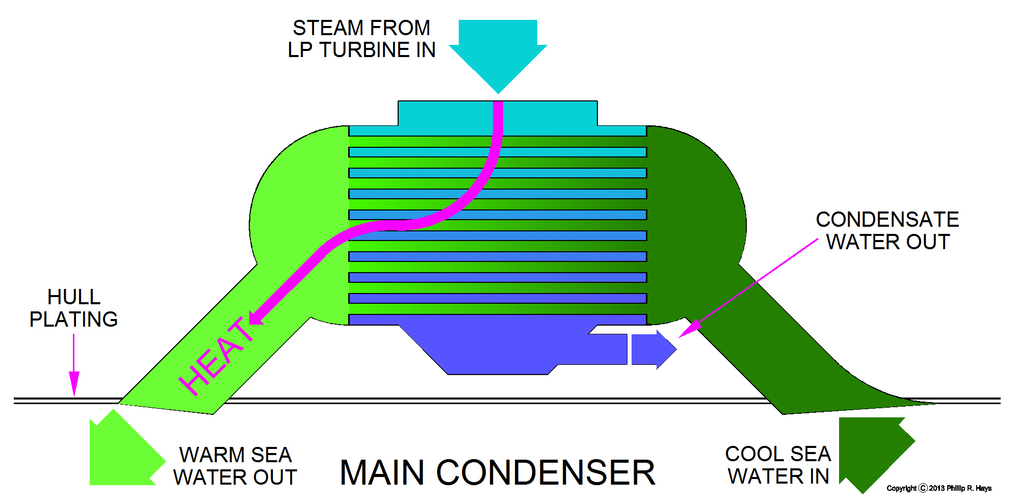
Sea water entered the hull through 27 inch diameter main condenser inlet sea chests. The ship had a scoop injection system that protruded below the hull plating to scoop up water while the ship was moving forward. This had the advantage that the volume of cooling sea water was controlled by the speed of the ship, automatically increasing cooling at the time it was most needed. When the scoop system was not effective (while the ship was not moving, or moving backwards) the main circulating pumps circulated sea water through the condensers. The cool water flowed through the condensers in tubes where it absorbed heat from the steam. Then the warmer water flowed back out through the hull through the main condenser outlet sea chests. These sea chests had bars across the openings to keep out large marine animals and debris. Some of the bars could be removed to allow divers to enter the ducts for cleaning. The sea chests also had saturated steam flushing ports to blow away debris, marine animals like barnacles and clams and sea weed that might grow in the ducts.
Steam flowing around the cooling tubes lost heat and condensed into water that collected in the hot well at the bottom of the condenser, and then it was removed by the condensate pump. When steam condenses to water the volume decreases by several orders of magnitude. Within the confined space of the condenser this resulted in a vacuum. It was the vacuum created in the condensers that allowed the propulsion plant to work. A large pressure differential was maintained as high pressure superheated steam from the boilers flowed through the turbines to the low pressure vacuum in the condensers.
Steam lost energy to the turbines so the temperature and pressure dropped. However, since the system was closed (no discharge to the atmosphere) if the spent steam was returned directly to the boilers pressure and temperature would have equalized throughout the system and the turbines would not have worked efficiently, if at all. The efficiency of the system depended upon the temperature difference between the source (boiler) and receiver (condenser). Since the volume of the turbines and condensers was constant, pressure dropped proportionately with temperature. Cooling the steam/water as much as possible in the condensers produced the greatest efficiency in the system.
The highest possible vacuum must be generated in the condenser to produce the most efficient turbine operation. When the ship was operating at higher latitudes where the ocean is cooler the condensers operated at highest efficiency. In equatorial waters, where the ocean is warm, the condensers could not generate as high a vacuum and the system was less efficient.
The condensers had an expansion/contraction problem like the turbines. When the engines were started the condensers expanded as they were heated, and they contracted after the engines were shut down. The condenser shell had expansion joints, as did the attached steam and sea water piping. The condensers were attached to the Low Pressure Turbine and shared its mounting to the hull structure.
Feed Water Circulation
After the steam passed through the turbines it could have been exhausted to the atmosphere to create the temperature/pressure differential across the turbines without using an elaborate set of condensers and pumps. Many small steam engines and steam powered locomotives operated this way. However, the ship's boilers had to produce large amounts of steam to propel the turbines, and that required large amounts of very pure boiler feed water. Sea water could not be used as boiler feed because it contains salts and minerals that would erode the generating tubes in the boilers causing them to fail. Feed water was produced by distilling sea water to eliminate the impurities. A very large distillation plant and huge amounts of energy would have been required to distil enough pure feed water for the boilers to keep the turbines spinning. It was much more efficient to recover the spent steam and reuse the pure feed water. Only relatively small amounts of feed water had to be distilled to replace steam that leaked out of the system.
Gasses (especially oxygen) must not be allowed to accumulate in the system. The condensers had air ejectors to remove gasses that accumulated above the level of condensation. The air ejectors also served to create the initial vacuum when the engines were started (condensation of steam was not sufficient to create a vacuum in a cold system). Steam and air from the Main Condensers was piped to air ejectors where the gasses were mixed with saturated auxiliary steam. The hot steam/water mixture passed through a small condenser where the steam condensed to water. The cooled condensate water from the Main Condensers flowed through the Air Ejector Condensers to cool them. The water from these condensers was returned to the Main Condensers for cooling and recirculation. The gasses from the air ejectors were vented to the atmosphere. After passing through the Air Ejector Condenser the condensate from the Main Condensers mixed with the condensate from the turbogenerator Auxiliary Condensers and then flowed into the Deaerating Feed Tanks.
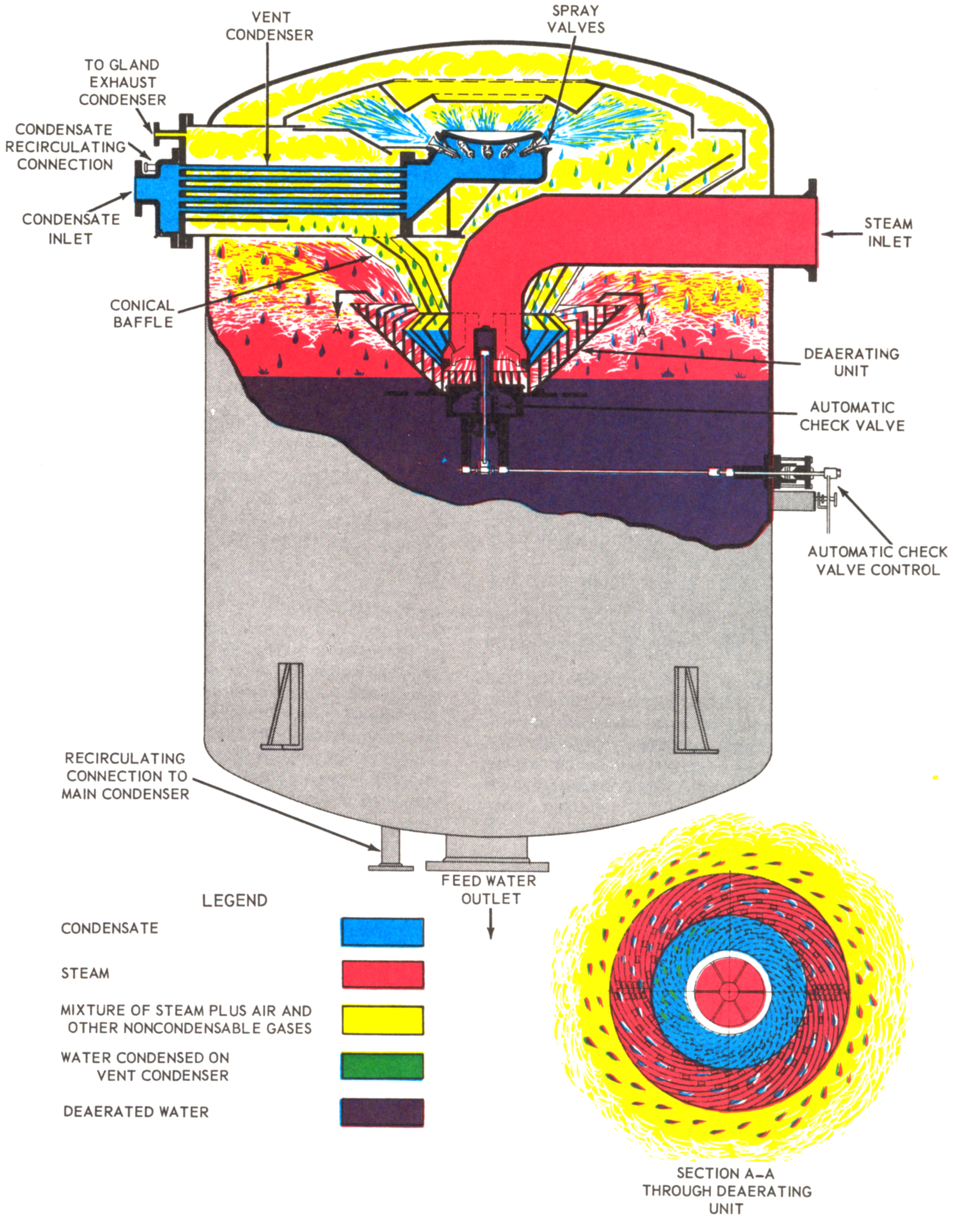
The Deaerating Feed Tanks degassed and stored feed water for the boilers. The water was heated by saturated auxilliary steam from the boiler steam drum. Cool condensate was sprayed into the steam filled upper portion of the tank. The steam cooled and condensed into water and drained into the central cone-shaped baffle, and from there into the deaerating unit. There the water was thrown outward into the curved baffles where it lost dissolved gasses, removing all traces of dissolved oxygen. The deaerated water fell into the storage space at the bottom of the tank. This was the reservoir of feed water for the boilers. If the water level in the deaerating feed tank got too high the tank would not deaerate the water. If the level was too low a sudden demand for feed water might drain the tank, and that could cause problems with the feed water pumps and the boilers.
The Feed Booster Pump removed water from the bottom of the Deaerating Feed Tank and provided a positive pressure head for the Main Feed Pump to prevent the hot water from flashing into steam in the pump. The Main Feed Pump ran at variable speed to keep a constant pressure to the steam drum. The pump pressure was higher than the steam drum pressure, ensuring a continuous flow of feed water to the boiler.
Reduction Gears
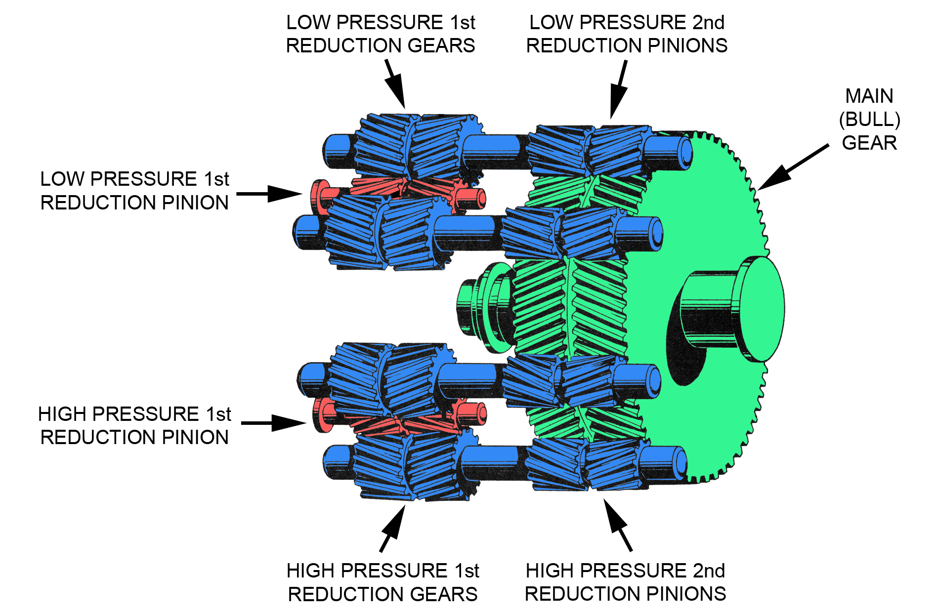
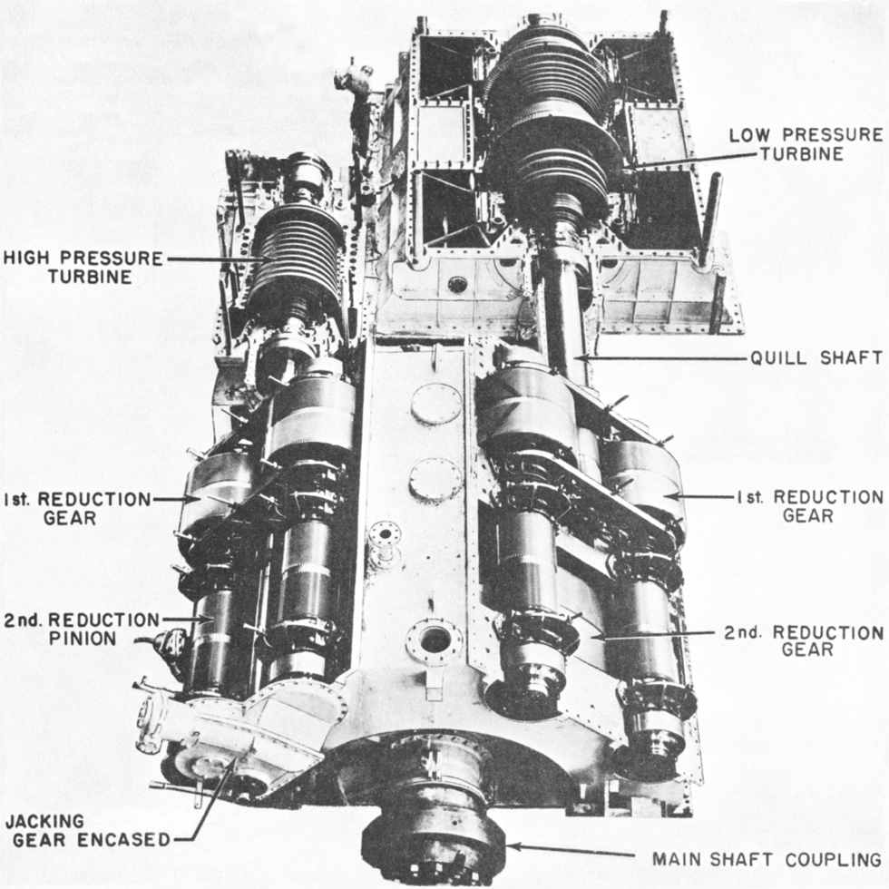
Steam turbines operate most efficiently at high rotation speeds, and propellers operate efficiently at much slower rotation speeds. Reduction gears are used to allow both the turbines and propellers to operate at their most efficient speed ranges. The reduction gears were double helical gears (herringbone gears) because they run smoother and produce no end thrust. The OK City had a double reduction gear where the 1st Reduction Pinion gears connected to the turbines drove two reduction gear shafts. On the other end of these shafts was a 2nd Reduction Pinion gear that drove the Main Gear (Bull Gear). The Main Gear was connected to the propeller shaft.
The illustration shows a locked train double reduction gear. The primary drive pinions from the high pressure turbine and low pressure turbine are shaded red, the secondary reduction gear shafts are shaded blue, and the main gear is shaded green. On the Oklahoma City each reduction gear assembly was 10' long, 11' wide, 10' 4" high, and weighed 62,000 pounds. The main gear was 7' 11.472" diameter and 2' 5 1/2" thick.
| Item | SHP at Normal Power | RPM |
|---|---|---|
| HP Turbine | 11,550 | 5,882 |
| HP Secondary Shaft | 5,775 | 2,614 |
| LP Turbine | 13,450 | 4,705 |
| LP Secondary Shaft | 6,725 | 2,614 |
| Main Gear | 25,000 | 350 |
The table gives relative data for the reduction gears, showing speed and shaft horsepower at maximum speed. The primary shafts rotated at the speed of the turbines. The first speed reduction occurred in the 1st Reduction Gears - the HP side secondary shaft rotated at 45% of the HP Turbine speed, and the LP side secondary shaft rotating at 55% of the speed of the LP Turbine. The second speed reduction occurred where the 2nd Reduction Pinions drove the Main Gear. Both secondary shafts rotated at the same speed. The Main Gear rotated at 13% of the speed of the secondary shafts, or at 6% of the HP Turbine speed and 7.4% of the LP Turbine speed. The gear ratio from the HP 1st Reduction Pinion to the HP 1st Reduction Gear was 1:2.25 and the LP 1st Reduction Pinion to the LP 1st Reduction Gear was 1:1.8. The gear ratio from the HP and LP 2nd Reduction Pinions to the Main Gear was 1:7.47.
Propeller Shafts and Propellers
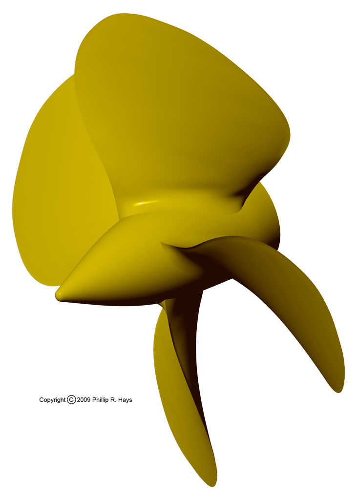
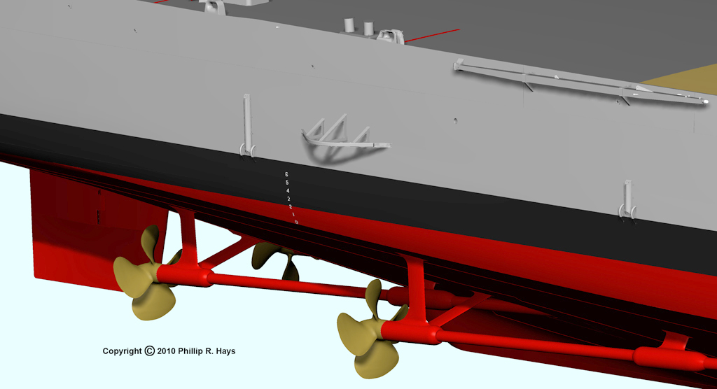
The ship had four different proportional pitch propellers. The propellers were 11' 10" diameter and weighed 14,930 pounds each. The port side propellers had left hand (counterclockwise) pitch and the starboard propellers had right hand (clockwise) pitch. The blades of the outboard propellers had about 0.75% greater area than the blades of the inboard propellers and had slightly greater pitch. The inboard propellers were positioned slightly lower than the outboard props where water was a bit denser, making the inboard propellers slightly more effective than the outboard propellers. To compensate and give the outboard propellers equal push the blades we made a bit wider so they could move more water. Each propeller had a serial number. Initially one set of spare propellers was made for each ship.
"Proportional pitch" means that the angle of the blade relative to the axis of rotation changed, being greatest near the hub and less farther out near the tip of the blade. The farther out from the center of rotation the faster the blade moved through the water, generating greater thrust near the tip of the blade for a given blade angle. To compensate for this difference the pitch of the blade was greatest near the axis of rotation to increase the effectiveness. The pitch was reduced with increasing distance from the axis of rotation in order to produce an equal amount of thrust over the entire blade surface. This design made the propellers more efficient when the ship was moving forward, but it reduced the effectiveness of the propellers when "backing down" or spinning in reverse.
The faster the propellers rotated the more push they generated, propelling the ship faster. As a general rule of thumb the ship moved forward one knot (one nautical mile per hour, or 1.151 miles per hour or 1.852 kilometer per hour) for every 10 to 11 RPM. 60 RPM would propel the ship at 6 knots, and 350 RPM (maximum speed) would move the ship at 32 knots (37 mph or 59 kph).
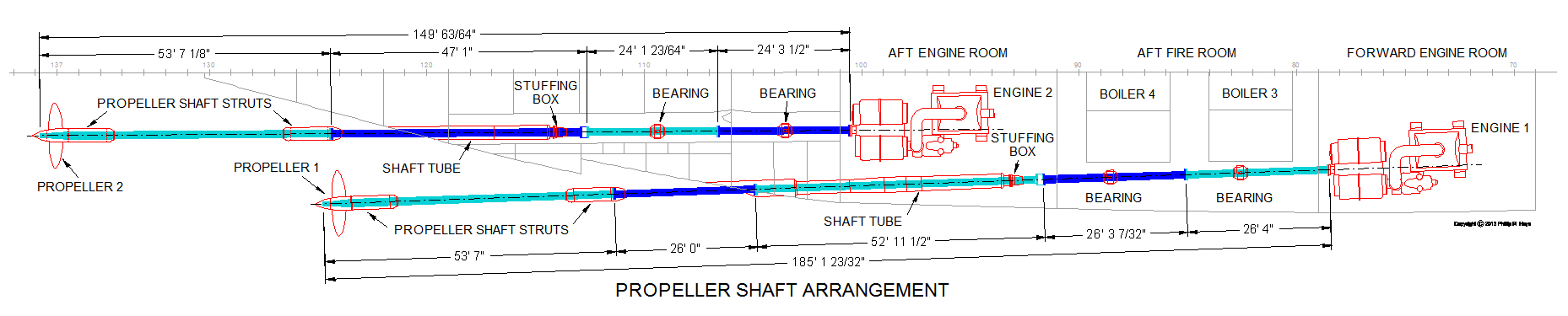
Rotation of the Main Gear was transferred to the propellers through the propeller shafts. Inside the hull the propeller shafts were supported by bearings in spring blocks. Outside the ship the shafts were exposed to the sea except where they were supported by bearings in the forward and after propeller struts. The shafts passed through the hull through water tight stuffing boxes and into shaft tubes opening into recessed wells in the hull. The inboard shafts passed through narrow shaft alleys from the after engine room to a short shaft tube. Outboard shafts passed through the After Fire Room and then into the After Engine Room where the shafts entered a long shaft tube leading to the hull openings.
The propeller shafts were made up of several sections bolted together at flanges. These were hollow tubes 15 1/2" outside diameter and 10" inside diameter. The inboard shafts were 149 feet long and were divided into four sections. The outboard shafts were 185 feet long in five sections. These sections could be separated for "unshipping" the shafts if part of the shaft had to be replaced. The section lengths were designed along with the shaft support bearing and strut positions so it was possible to remove single sections of the shaft without disassembling the entire assembly.
The shaft support bearings were mounted so they could be adjusted to reduce vibrations, and the propellers and shafts were balanced. However, the propellers and shafts generated quite a bit of vibration at higher speeds. At 32 knots the vibrations were noticeable throughout the ship, and were especially strong in the missile warhead magazine located between the inboard shaft alleys. At full speed the main deck at the stern vibrated strongly enough that small objects would bounce wildly on the deck.
The propeller struts supported the shafts outside the hull. The struts had a cylindrical hubs about 7 feet long and 2 1/2 feet diameter that contained bearings for the shafts. The forward struts were supported on a single strut arm and the after struts had two strut arms. These arms were attached to the internal framing of the ship. The arms were streamlined in cross section, and the pitch of the arm twisted from the hull surface out to the hub, aligned with the direction of water flow around the arm to minimize drag. The struts were large single piece steel castings with arms up to 12 feet long. After they were mounted on the ship they were bored in place for the shaft bearing mounts. The fore and aft ends of the forward struts and the forward end only of the after struts were streamlined with a two piece removable fairwater that fit around the shaft. The forward fairwater on the forward struts enclosed flanges where the after two propeller shaft sections were mated.
The outboard propeller blades extended beyond the sides of the hull. Propeller guards on the hull sides prevented the ship from coming too close to piers and other ship's hulls to protect the props from damage.
Additional Equipment
The basic diagrams and text for the propulsion system describe only the major pieces of equipment. Occasionally a pump or other device might be mentioned, but as some of the more complex diagrams show the ship had far more individual pieces of equipment. Part of this was due to the requirement for backup systems in case something was damaged in combat, so duplicate equipment was placed in the fire rooms and engine rooms. All major systems had duplicate steam and electric motor driven pumps, and some also had hand driven pumps. Another reason for duplication was the need to cold start the entire plant. When the boilers were cold there was no steam to power the steam turbine driven pumps and electrical generators and there was no vacuum in the condensers to start the propulsion turbines. The ship had equipment to produce the start-up conditions without steam. After one boiler was fired it produced steam to start up additional boilers and power generators. There were dozens of pumps in the engineering space, and dozens more throughout the ship.
Diesel generators provided a limited amount of power to drive electric motor driven pumps to get fuel and feed water circulating. Diesel engines were started with compressed air from reservoirs. Air compressors charged these reservoirs and provided compressed air for many other ship's systems. Diesel fuel day tanks provided fuel for the generators. A lubricating oil system supplied the pumps, turbines and generators. These included lube oil pumps, strainers, coolers and storage tanks. The fuel oil system for the boilers included fuel oil hand pumps, fuel oil strainers and fuel oil heaters. Air ejectors removed gasses from the main condensers and also produced the initial partial vacuum in the condensers to start the turbines. Fire and flushing pumps provided sea water to the shipboard fire fighting system and the water wash down system. The fire rooms contained a CO2 fire suppression system. A ventilation system blew cool air into the spaces for the crew to breathe. All of these pieces of equipment were connected with a maze of piping and valves. Between all of this equipment were catwalks and ladders so the crew could move around.
References
1. Principles of Naval Engineering, NAVPERS 10788-B, Bureau of Naval Personnel,1970.2. Express Type Boiler, Babcock & Wilcox drawing MX-242901-9, National Archives microfilm Reel 5537, Frame 3032, 1940.
3. Blueprints for the original Cleveland class ships and for the CLG Talos modifications.