
Many types of equipment are powered by hydraulic pumps and motors. An electric motor, diesel engine or steam turbine running at constant speed drives a hydraulic pump. The hydraulic pump converts the rotary motion of the driving motor into hydraulic pressure. The pressurized fluid drives a hydraulic motor or hydraulic cylinders. The hydraulic motors convert pressure into rotary motion, typically at much lower rotation speed than the original electric, diesel or turbine engine. Hydraulic cylinders convert pressure into linear motion.

When hydraulic pumps and motors are connected they are referred to as a hydraulic transmission. The pump is called the "A end" and the motor is the "B end." This arrangement has several advantages. First, the electric motor, diesel engine or steam turbine can run at an optimum speed where it operates efficiently. The pressurized hydraulic fluid can be piped long distances without losing much energy to the surroundings. Hydraulic motors are relatively small but can deliver great power. The hydraulic transmission can operate over a wide range of speeds and the speed can be controlled very well over the full range. They have a high starting torque and can accelerate to full speed very quickly. They also provide a strong holding force when they are not turning. These features make them the best choice for powering many types of shipboard equipment.
Rotary Hydraulic Pumps
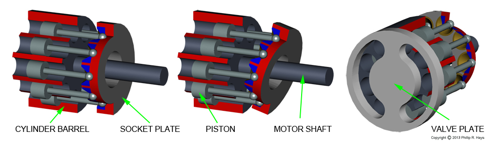
The illustration shows an axial-piston variable stroke (variable displacement) hydraulic pump. The driving motor turns the motor shaft that connects to a socket plate and a cylinder barrel. The rotating cylinder barrel has nine cylinders and pistons. Each piston has a connecting rod linking it to the rotating socket plate. These elements turn inside a non-rotating pressure housing that has a valve plate on the end.
The key to the operation of the pump is the socket plate. It spins with the motor shaft and is connected to the shaft through a universal joint so it can tilt in any direction while it rotates. A non-rotating variable tilt plate (see the first picture on this page) controls the angle of the socket plate to the motor shaft. The socket plate rides on a thrust bearing on the tilt plate so the angle of the socket plate matches the angle of the tilt plate. The socket plate continuously pivots around the connection to the the motor shaft as it rotates. The angle of the variable tilt plate can be adjusted to control the output of the pump. Separate stroking pistons change the angle of the variable tilt plate to control the pressure generated by the pump.
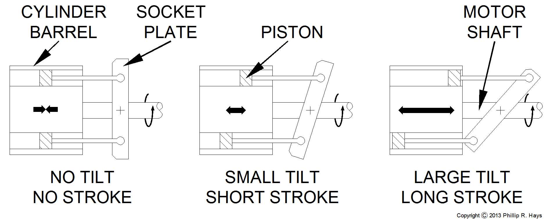
If the socket plate is perpendicular to the axis of rotation the pistons do not move in their cylinders. This is the neutral position where no fluid is pumped and no pressure is generated. When the socket plate is tilted it spins at an angle to the motor shaft so the distance from a socket to the cylinder barrel changes continuously. The pistons move back and forth in their cylinders as the assembly rotates, pulled by their ball and socket connections to the socket plate. This forces hydraulic fluid though the opening in the valve plate, increasing pressure in the hydraulic drive lines. The greater the tilt angle the longer the piston stroke, and the more hydraulic fluid that is pumped.
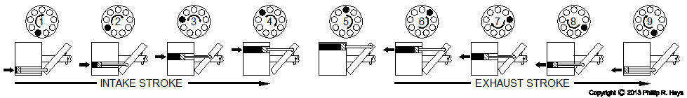
This diagram follows one piston as it rotates through a full circle around the motor shaft. At the start of the intake stroke the piston begins to move into the cylinder, pulling in hydraulic fluid through the opening in one side of the valve plate. As the assembly rotates through half a rotation more and more fluid is drawn in until the piston reaches the maximum extent of its motion, as determined by the angle of the socket plate. Then as rotation continues the piston is forced back through the cylinder, expelling the fluid on the exhaust stroke through the other opening in the valve plate. Since there are many pistons in the assembly, at any time some are drawing in hydraulic fluid from the drive line pipes on one side of the valve plate and others are expelling it into the drive line pipes on the other side of the valve plate. This provides a continuous flow of fluid with minimal pressure fluctuations.
By controlling the angle of the variable tilt plate (which controls the angle of the socket plate) the output of the pump can be varied from nothing to full flow. Because the hydraulic fluid is not compressible all of the power of the moving pistons is converted to pressure. Even when the tilt plate is in the neutral position the pump still exerts control because the hydraulic fluid is not compressible - whatever is connected to the other end of the pipes cannot move. This is called "hydraulic lock."
The capacity of a pump is equal to the displacement of each cylinder multiplied by the number of cylinders multiplied by the speed in rotations per minute (RPM). The displacement of each cylinder is controlled by the tilt angle. Since RPM is normally constant, output capacity is controlled entirely by the tilt angle. The variable tilt plate can be rotated from the neutral (perpendicular) position in two directions. When tilted one way the pump sucks in fluid from one opening in the valve plate and discharges it through the other. If the tilt plate is tilted in the opposite direction the operation is reversed. This makes the pump reversible, a very handy feature for driving motors and hydraulic rams. Direction and speed of pumping is controlled by the variable tilt plate.
Hydraulic Motors
A hydraulic motor is just a rotary hydraulic pump with the tilt plate in a fixed position (fixed displacement motor). It works just the opposite of the rotary pump. Pressurized fluid enters through the opening in the valve plate and forces the pistons to move through the cylinders. This pushes on the socket plate causing it to rotate around the motor shaft. The socket plate drives the motor shaft causing the cylinder barrel and the motor shaft to turn.
Most hydraulic motors differ from pumps in one very significant way. Hydraulic fluid is introduced to both sides of the pistons in the cylinders. Basically the motors have two valve plates on opposite ends of the cylinder barrel and these are cross connected so when one side of the cylinder is on the exhaust stroke the other side of the same cylinder is on the input stroke. This effectively doubles the power of the motor.
Motors and pumps do not necessarily have the same piston diameters. If the motor has smaller pistons than the pump it will spin faster, and if the motor pistons are larger it will spin slower. The ratio of the diameters of the pump and motor pistons determine the mechanical advantage of the system. The larger the motor pistons the slower the motor will rotate but the greater power it will have.
Like the pump, the operation of some motors can be controlled by varying the angle of the tilt plate. This allows multiple motors to be driven from a single pump with each motor's speed independent of the other motor speeds. These are variable displacement motors.
Hydraulic Cylinders
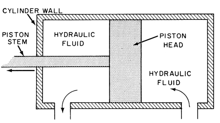
Hydraulic cylinders (hydraulic rams) convert pressure into linear motion and can deliver great amounts of force to move massive objects. Operation is pretty simple. Hydraulic fluid is pumped into one end of the cylinder under pressure. Force exerted on the piston causes it to move. To reverse the motion fluid is pumped into the other end of the cylinder causing the piston to move in the opposite direction. When fluid is pumped into one end of the cylinder fluid is sucked out of the other end and returned to the pump or fluid reservoir.
The piston pushes and pulls the piston stem or rod which is connected to the object to be moved. The amount of force on the rod is equal to the pressure of the fluid multiplied by the surface area of the piston in contact with the fluid. For a given fluid pressure larger diameter pistons generate more force than smaller diameter pistons. Because one side of the piston connects to the rod the fluid contact surface area is smaller than the other side, so the cylinder generates different forces on the extension and retraction strokes.
Hydraulic Accumulators
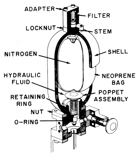
Hydraulic accumulators are used to smooth out pulsations in the fluid supply and to provide fluid for sudden short term demands. Accumulators on the OK City were mostly compressed gas types. Inside the accumulator tank is a flexible bag filled with compressed gas, typically nitrogen. Nitrogen does not create a fire hazard when exposed to oils. Around this bag is hydraulic fluid from a connection to a hydraulic line.
Hydraulic fluid is not compressible but the gas is, and energy is stored in the compressed gas. As fluid pressure increases the volume of the gas decreases, compressing the gas until gas pressure equals fluid pressure. This allows more fluid to flow into the tank from the hydraulic line. If the fluid pressure in the line drops the gas bag expands, driving fluid out of the tank until gas pressure equals fluid pressure. Accumulators absorb short pressure fluctuations to maintain even pressure in hydraulic lines.
Accumulators can deliver fluid at higher rates than pumps so they are often located near hydraulic devices that operate very quickly, such as hydraulic cylinders and high speed hydraulic pumps. The accumulator serves as a fluid reservoir and pressure booster. Rapid fluid flow from the accumulator maintains pressure in the hydraulic lines during sudden demands. In systems that operate only for short periods a relatively small low volume pump can be used to pressurize the system and an accumulator supplies the brief high volume surge of fluid needed to operate the equipment. The pump repressurizes the accumulator after the event.
Accumulators are connected to nitrogen tanks to allow the gas in the bag to be recharged to make up for any leaks. Even when the pump is not running the pressurized gas in the bag maintains pressure throughout the entire system. Occasionally it is necessary to perform maintenance that requires depressurization. For this the accumulator is isolated from the nitrogen supply and the pressurized nitrogen in the bag is bled off to the atmosphere.
References
1. Principles of Naval Engineering, NAVPERS 10788-B, Bureau of Naval Personnel,1970.2. Gunner's Mate Missile 3 & 2, NAVTRA 10199-B, Naval Training Command, 1972.