Radars
AN/SPS-43A
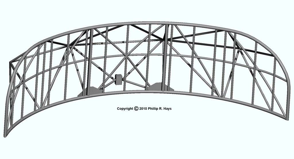
The AN/SPS-43A radar used a 41 foot wide AS-1092/SP "bedspring" antenna for long range air search, capable of detecting airborne targets out to a range of 300 miles. The antenna was mounted at the top of the forward radar tower about 106 feet above the ocean. The antenna had a radiation pattern with a 7° horizontal and 20° vertical beam width. It operated in the VHF band at 200 MHz with 180 kW peak output.
The shorter antenna at the top is an AT-352/UPA-22 IFF Interrogator antenna. Friendly aircraft and ships carried an IFF (Identification Friend or Foe) transponder that responded to an interrogation signal from the ship. The encrypted code identified the unit - no code meant the target might not be friendly (or the IFF transponder wasn't working). During the Vietnam War the ship also carried a secret Soviet IFF Interrogator that would cause enemy units to identify themselves. It was very useful for sorting out friendly and enemy aircraft over North Vietnam.
The antenna was a double corner reflector with a "W" shape in cross section. It had an array of ten pairs of dipoles fed by a complex coaxial transmission line system with power dividers to feed each pair of dipoles.
The antenna attached to a rotating turntable that rested on a pedestal. The pedestal sat on an elevated support base that also supported the drive motor.
AN/SPS-30
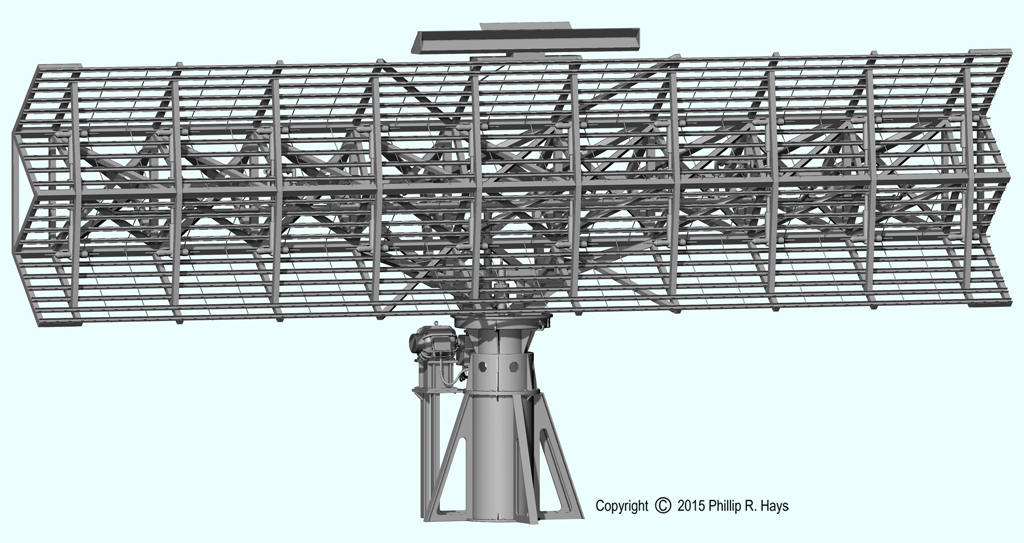
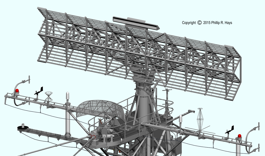
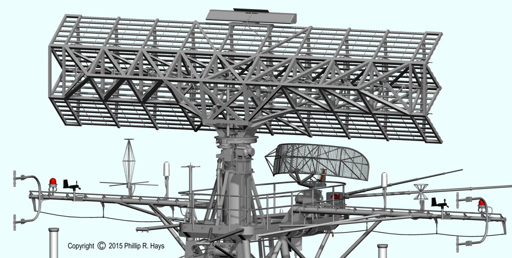
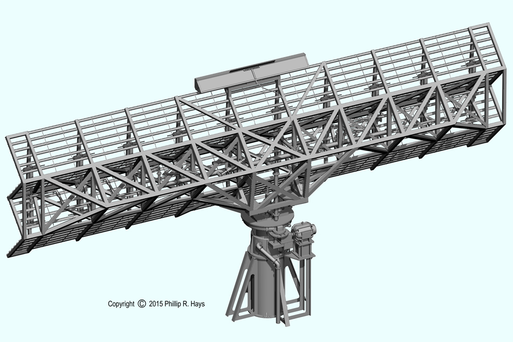
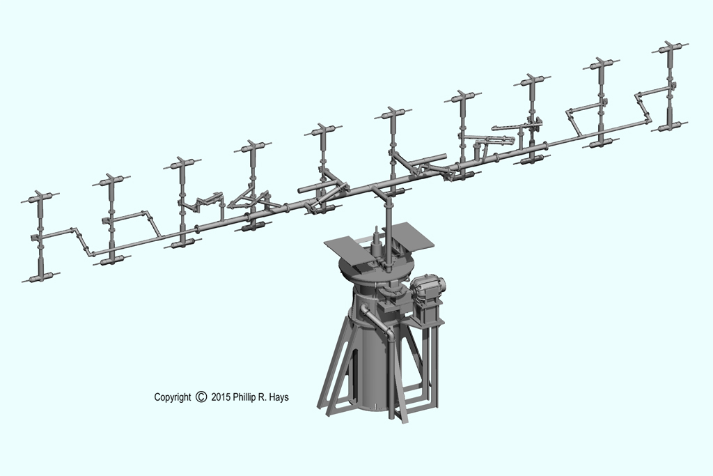
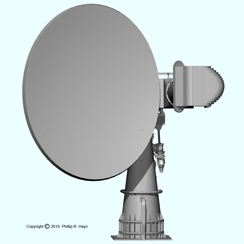
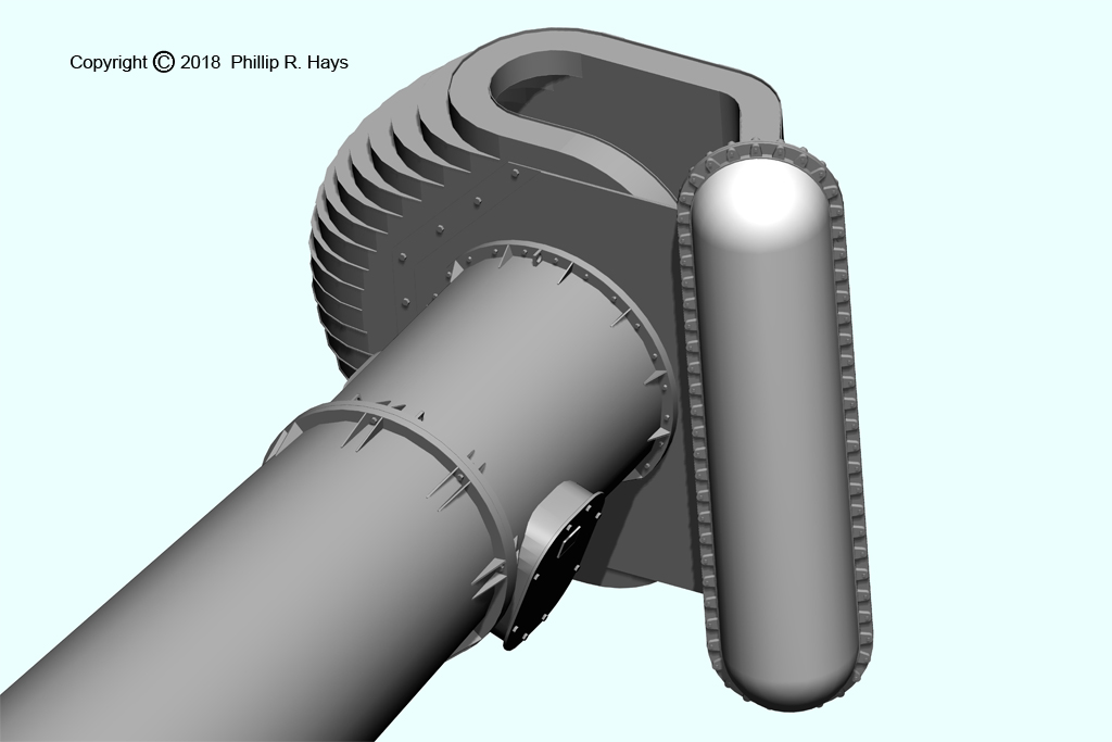
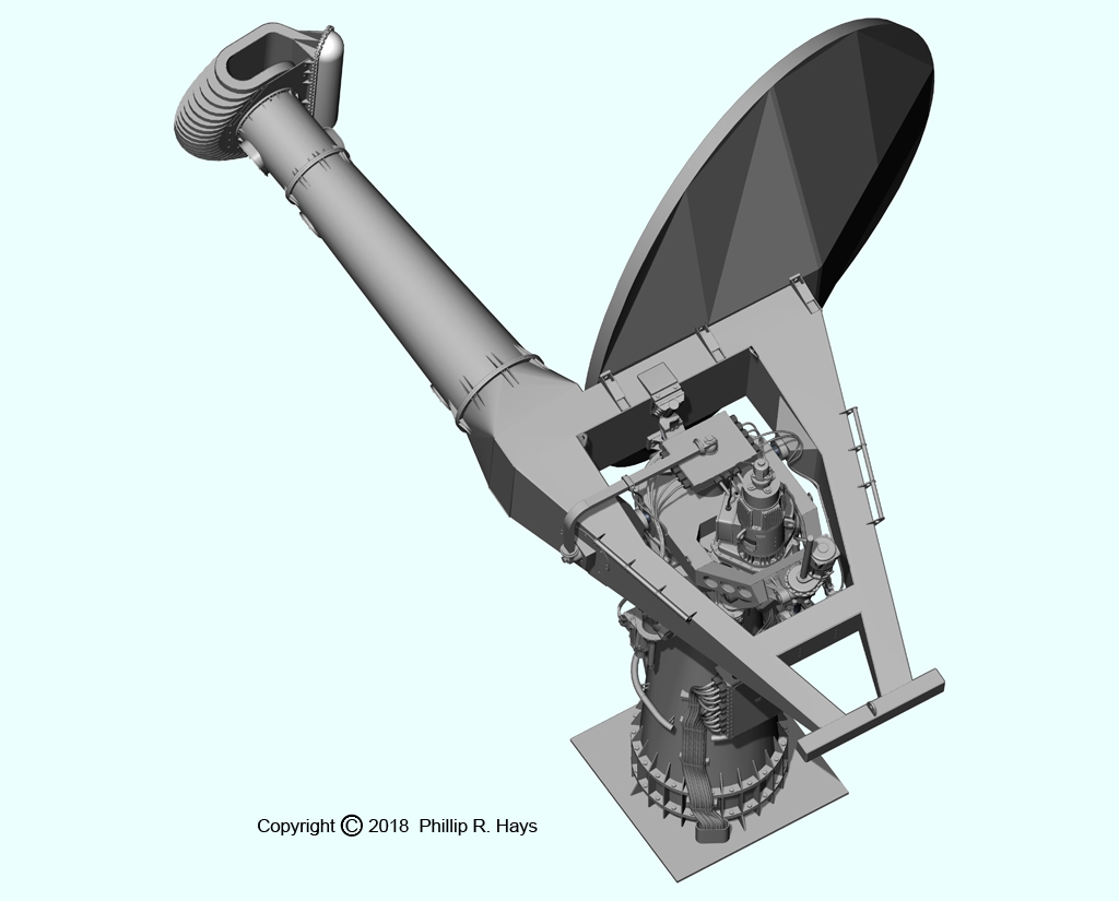
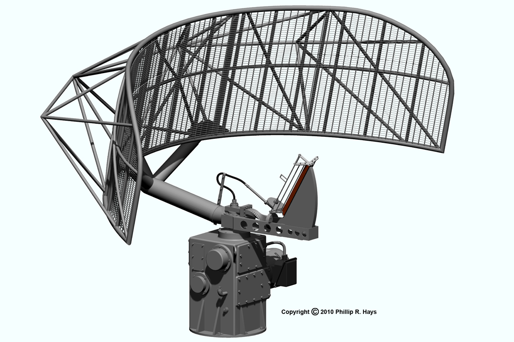
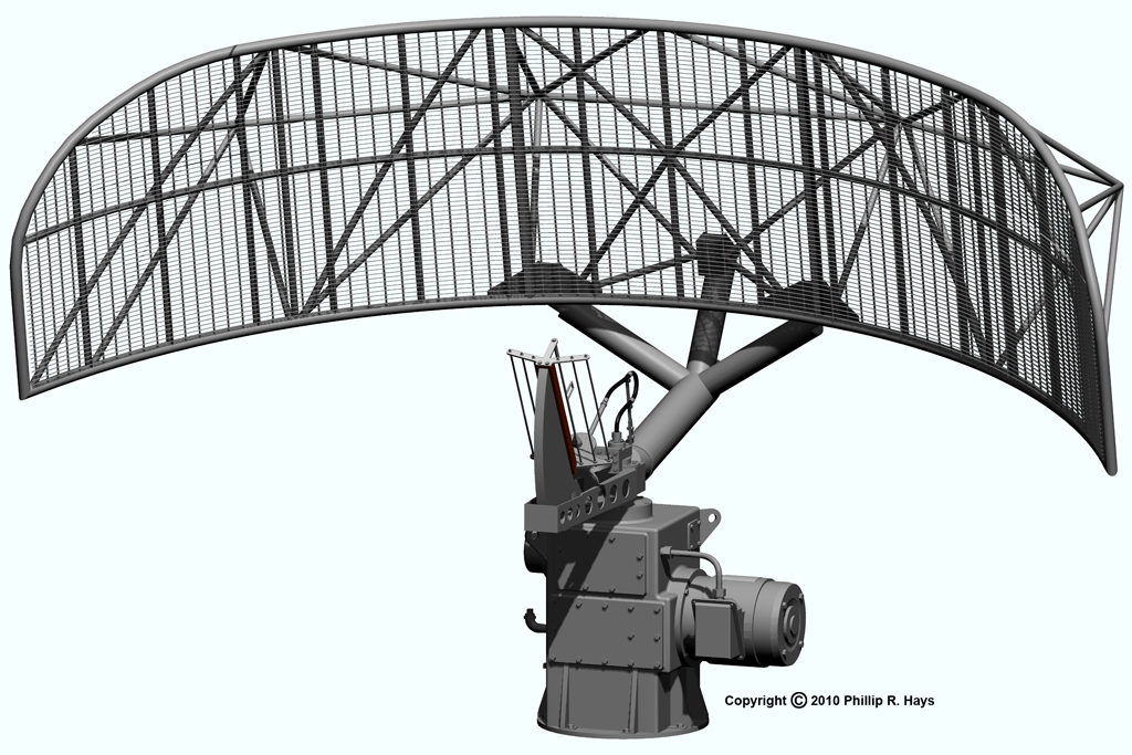
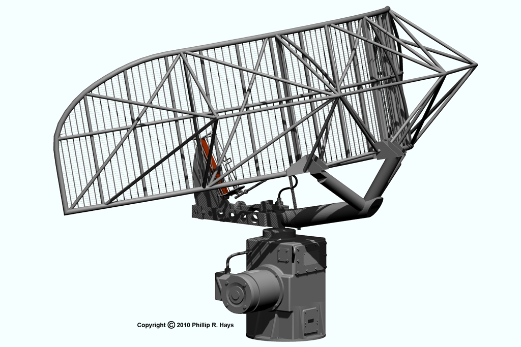
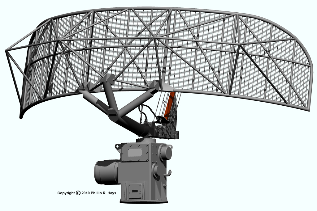
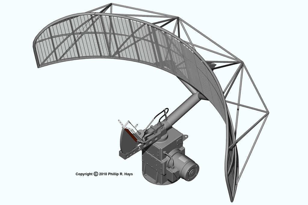
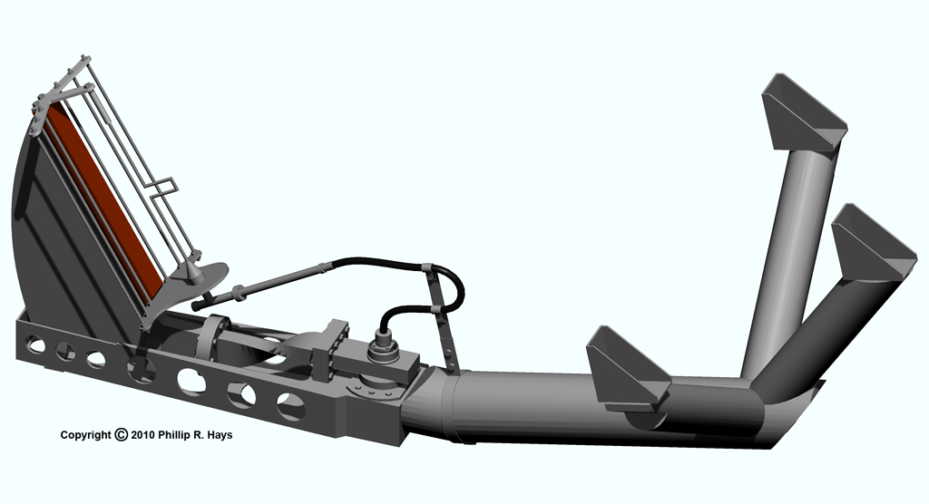
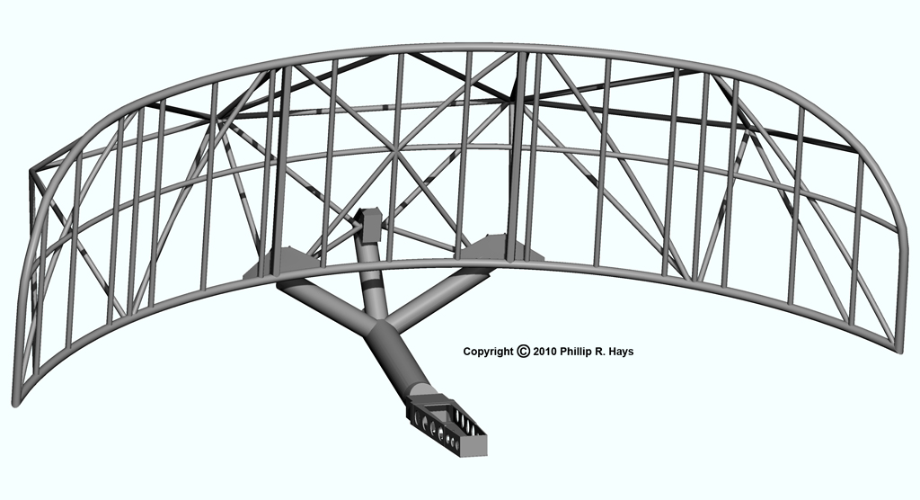
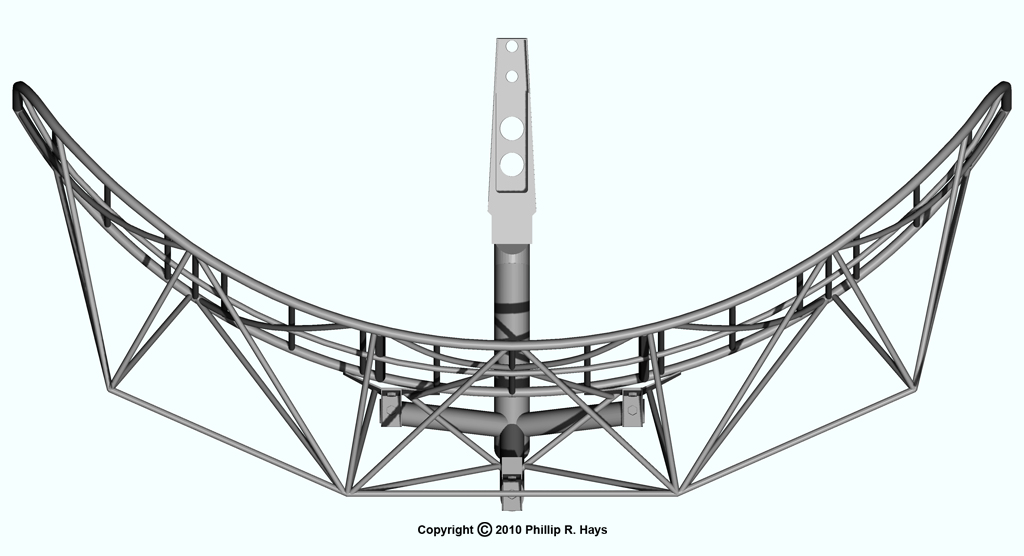
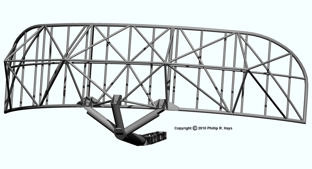
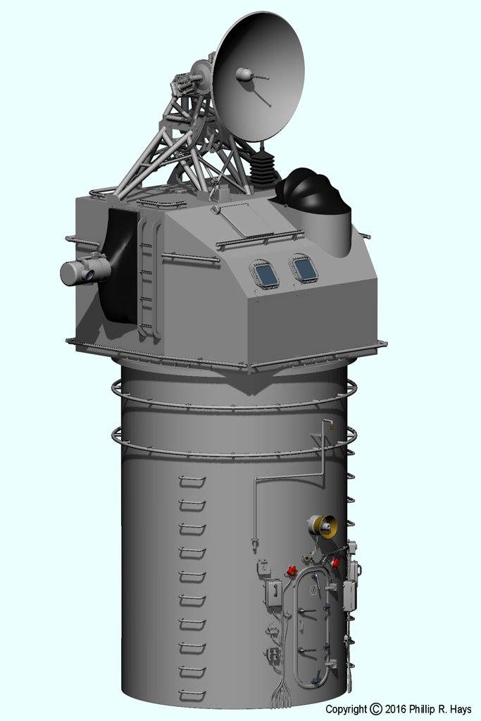
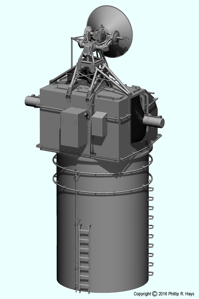
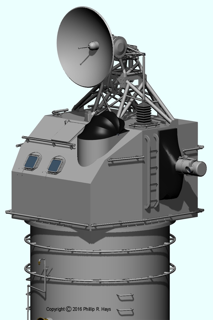
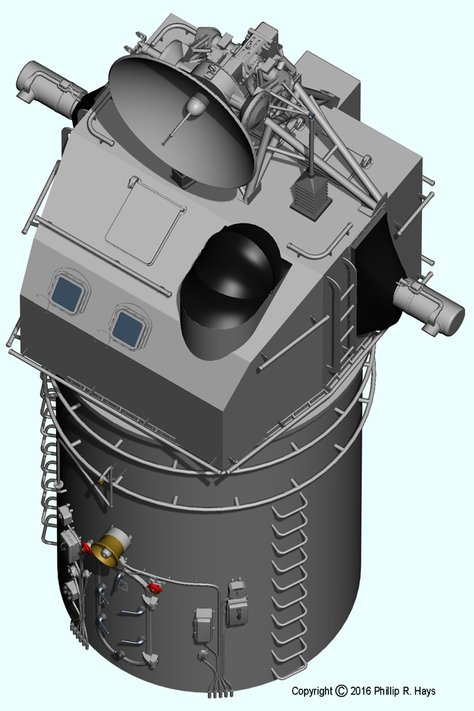
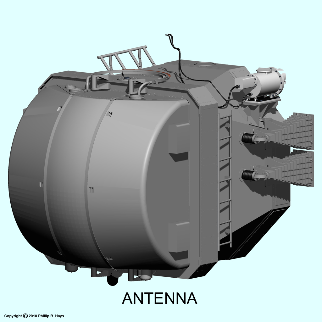
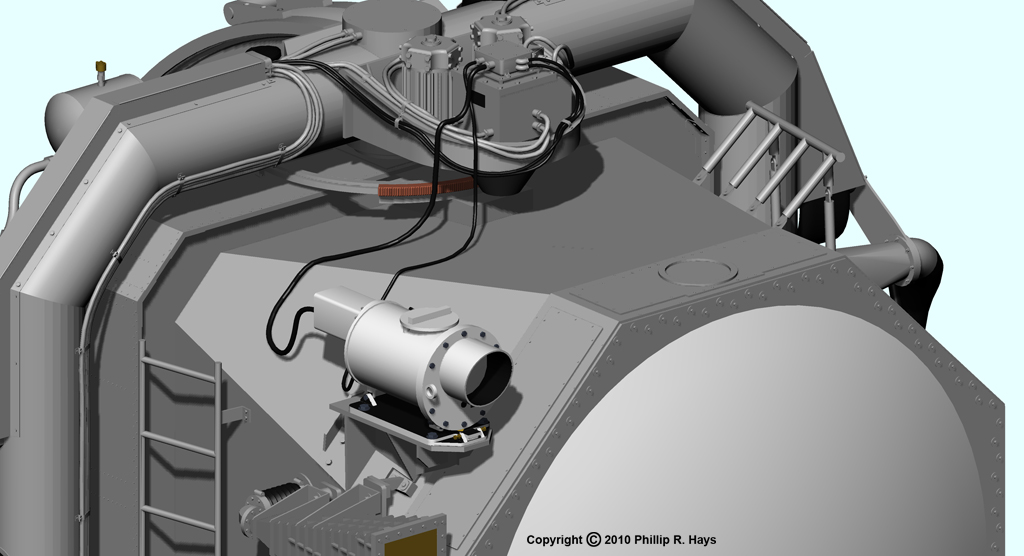
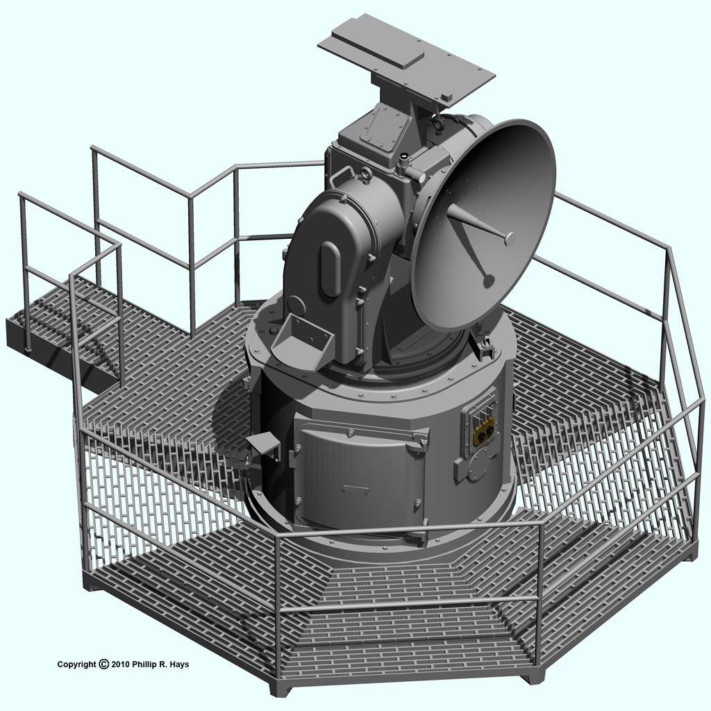
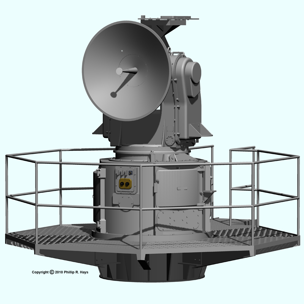
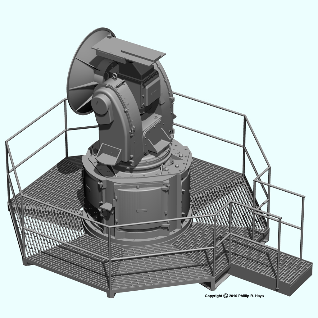
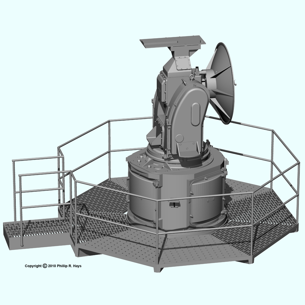
The AS-1167/SPS-30 antenna was used with the SPS-30 long range height finding radar. The antenna was mounted on the after radar tower about 81 feet above water. This 3-D air search radar provided range, bearing and height information for targets being tracked by the missile system. The principle elements were an elliptical parabolic reflector and an "organ pipe" scanner assembly at the end of the long arm extending in front of the reflector. Waveguides carried RF energy from transmitters below decks up to the scanner. A waveguide connection in the scanner rotating at 240 to 2400 RPM fed the RF energy into twenty parallel vertically stacked waveguides leading to the feedhorns. These transmitted and received at different angles to the reflector, producing multiple beams 1.2° high and 1.5° wide at different vertical angles. In addition the reflector and feed horn assembly could be elevated to track targets through a wide range of angles. The entire antenna rotated around the vertical axis. The SPS-30 operated in the S band from 3.4 to 3.6 GHz with a peak output power of 2.5 megawatts. It had an effective range of 240 miles. The CAD model is based upon installation drawings for the antenna, and is pretty accurate. I have close up photos of the antenna on the USS Little Rock museum ship that allowed me to add details to the model.
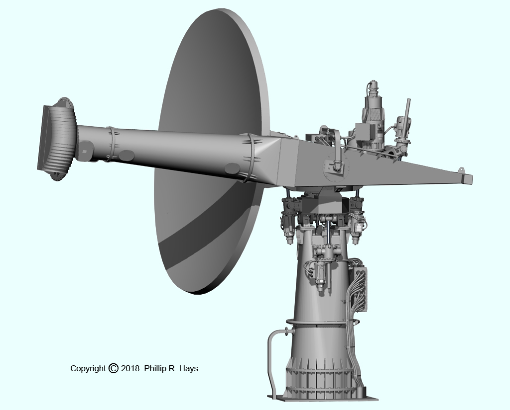
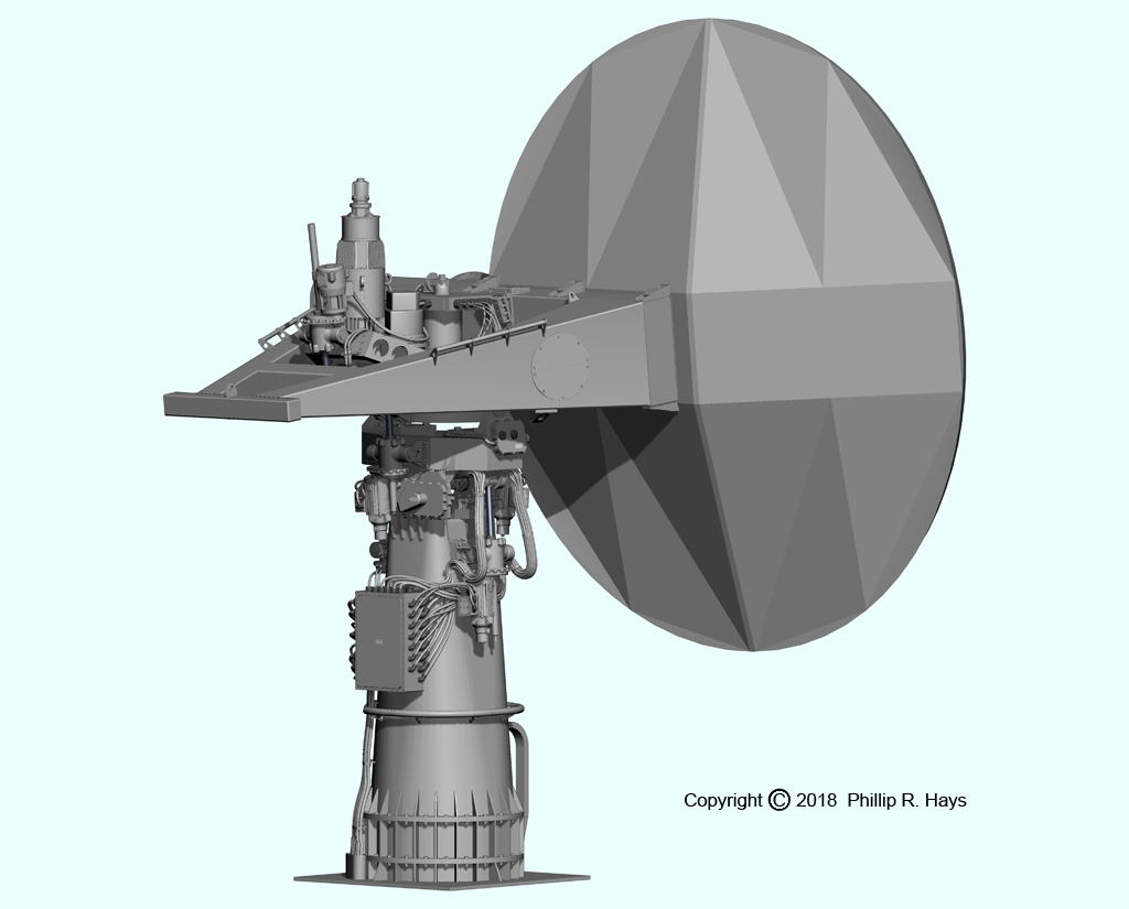
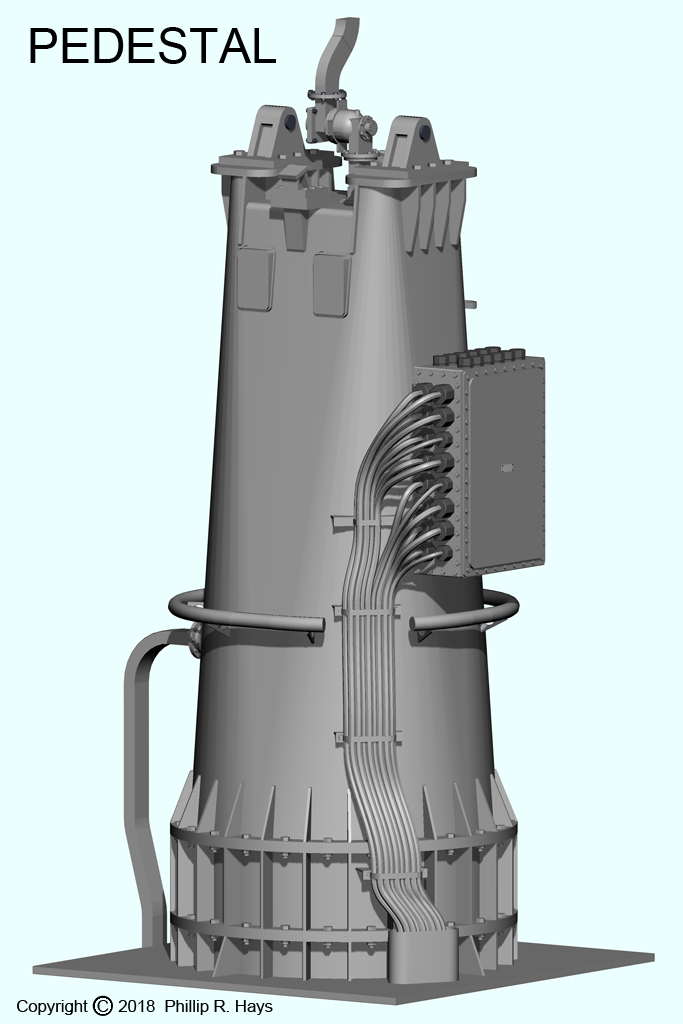
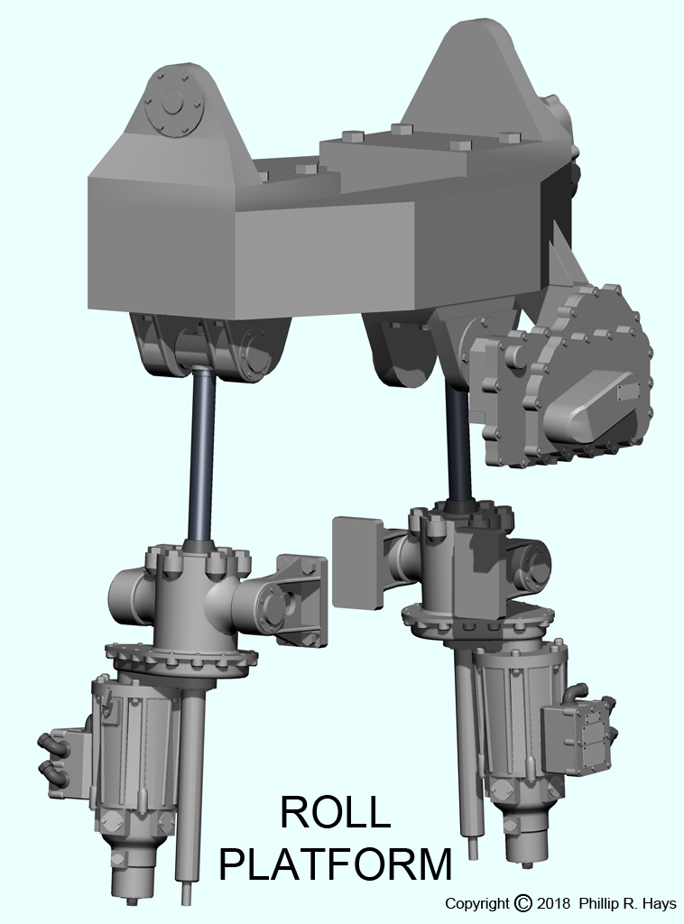
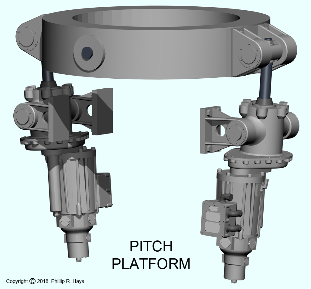
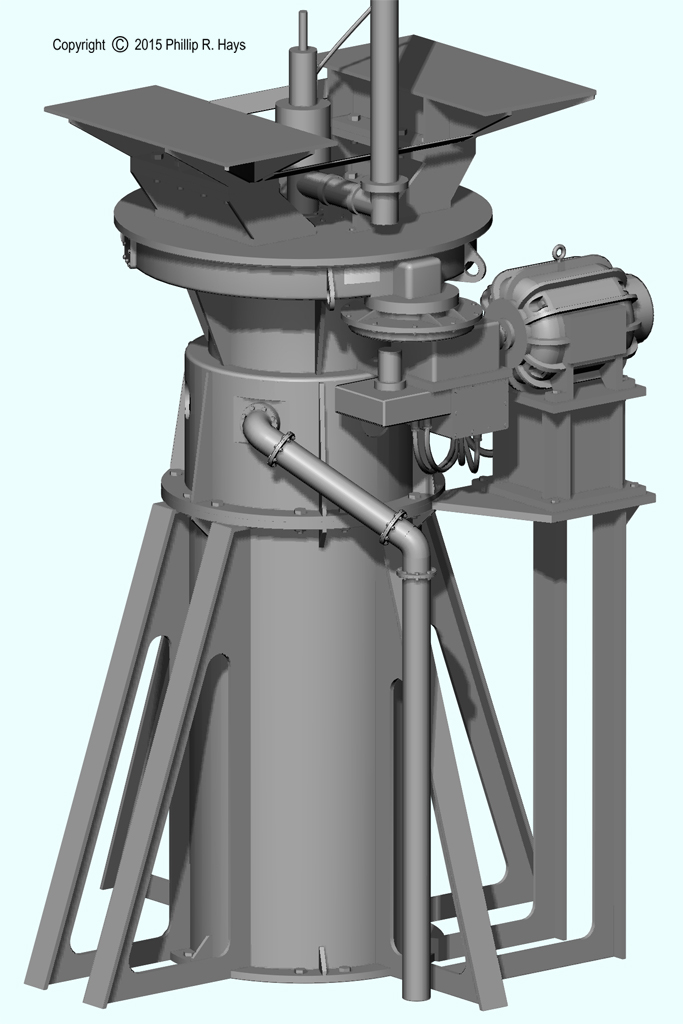
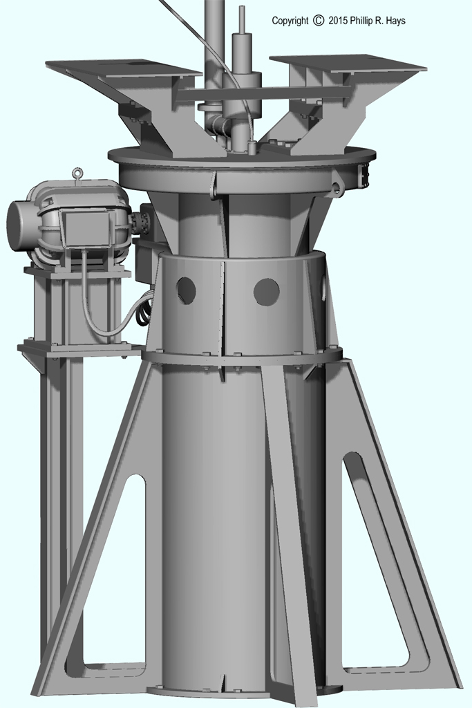
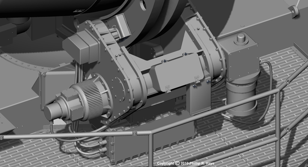
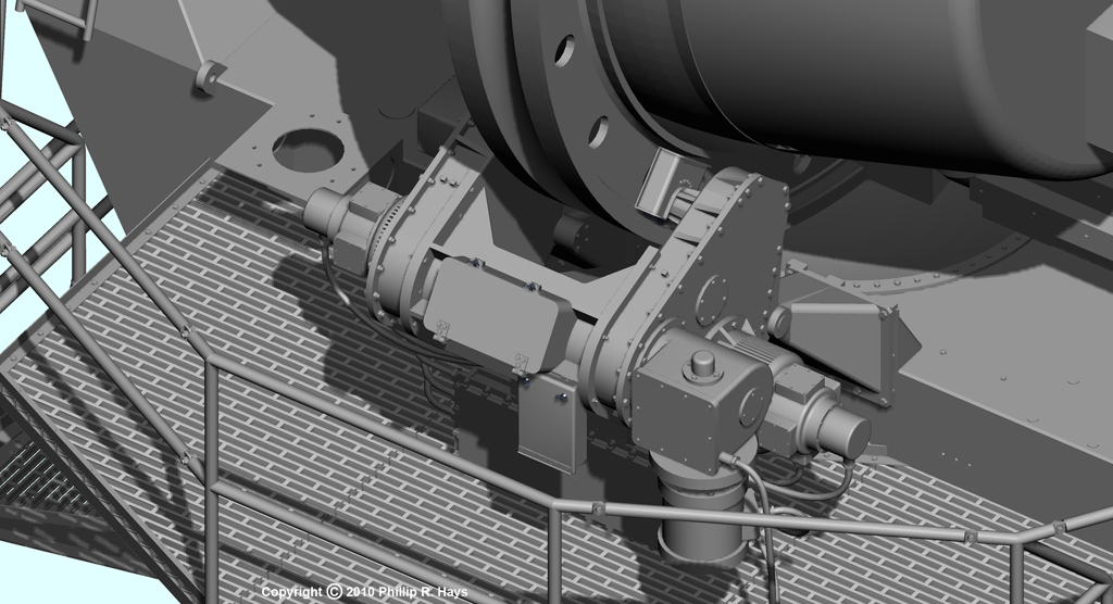
The antenna was mounted on a Pedestal that carried roll, pitch and elevation elements to provide a stable platform. Pairs of electric motors drove the Roll and Pitch platforms to compensate
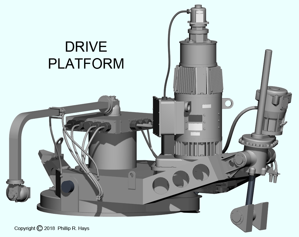
for ship motion up to 30° roll and 11° pitch. The Drive Platform rotated on the Pitch Platform.
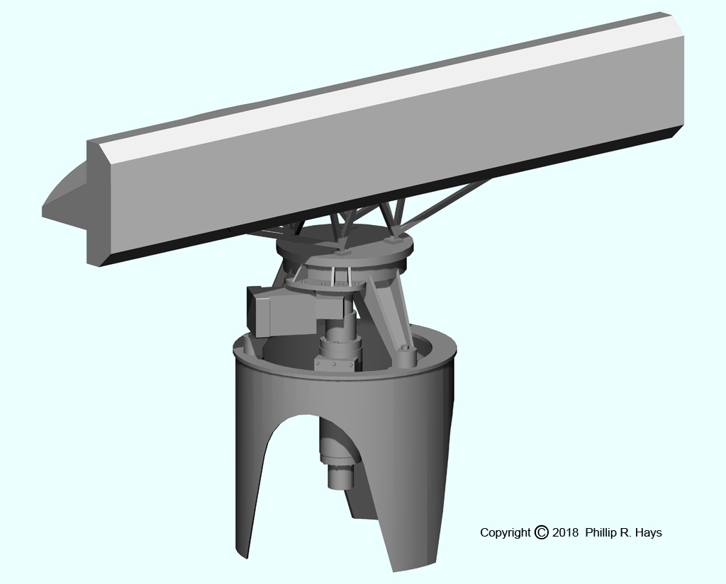 It carried a motor that controlled the elevation of the antenna from 6° to 30° above horizontal, and an azimuth motor that rotated the Elevation Platform around the vertical at five
speeds from one to ten revolutions per minute. Rotation could be stopped to follow a specific target, and the antenna could be oscillated about a bearing to sweep a wider sector. The "A" shaped
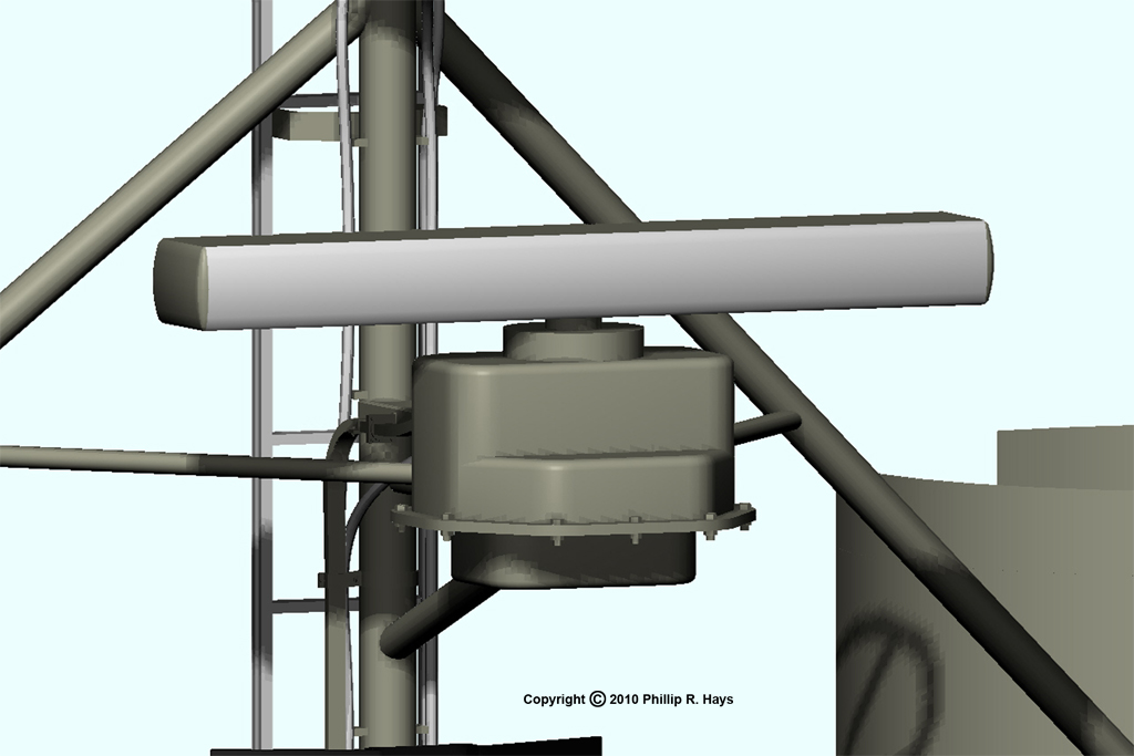
Elevation Platform pivoted on the drive platform and carried the reflector dish and the scanner mechanism. Cables and wave guides fed up from the Pedestal through the Roll and Pitch Platforms
into the Drive Platform. Rotating waveguide couplings and electrical slip rings transferred the signals to the square electrical box at the top of the Drive Platform.
It carried a motor that controlled the elevation of the antenna from 6° to 30° above horizontal, and an azimuth motor that rotated the Elevation Platform around the vertical at five
speeds from one to ten revolutions per minute. Rotation could be stopped to follow a specific target, and the antenna could be oscillated about a bearing to sweep a wider sector. The "A" shaped
Elevation Platform pivoted on the drive platform and carried the reflector dish and the scanner mechanism. Cables and wave guides fed up from the Pedestal through the Roll and Pitch Platforms
into the Drive Platform. Rotating waveguide couplings and electrical slip rings transferred the signals to the square electrical box at the top of the Drive Platform.
An AS-791/UPA-43 IFF Interrogator antenna located on the aft radar tower platform was slaved to the SPS-30.
AN/SPS-10A
The AN/SPS-10A was the ship's main surface search radar, and it also had a limited low altitude air search capability. It was mounted at the top of the forward radar tower forward of the SPS-43 antenna at 106 feet above the ocean. This model was created from dimensioned drawings in NAVSHIPS 0967-156-3040 Technical Manual for Antenna Assemblies AS-936( )/SPS-10B, and is fairly accurate. Additional details were taken from photos of the AN/SPS-10 on the USS Sullivans at the Buffalo and Erie Naval Park.
The antenna assembly consisted of a base gearbox and motor, the rotating "spider" which held the feedhorn assembly and supported the reflector. The reflector had a tubular framework that supported many "slats" that formed the reflector surface. A second tubular framework on the back of the reflector supported it and attached it to the spider.
The SPS-10 rotated clockwise at 15 RPM. The radiated beam was 16° high and 1.5° wide. The radar operated at 5.42 to 5.825 GHz with a 285 kW peak power. The antenna also carried an IFF dipole.
Pathfinder
The ship also had a small Pathfinder radar that was used for navigation. It was used mainly by the bridge watch to obtain radar bearing and range "fixes" for determining the ship's position in channels and harbors. The radar was mounted on the front of a light mast positioned on the O4 level just above the bridge, about 80 feet above sea level. This mast also carried navigation lights and antennas.
This is a "photoguestimation" model. I have found no really good photos and the radar unit has been removed from the USS Little Rock so I do not have a sample to measure. I don't even know the manufacturer (Raytheon?) or model number. Any information would be appreciated.
Directors
Mk 37
The Mk 37 director was used to control direct line of sight gunfire from both the triple 6"/47 turret and the dual 5"/38 gun mount. It carried both optical and radar systems to determine range, bearing and elevation to the target. The AN/SPG-25 radar antenna was slaved to the optical range finder sights extending from the sides of the director. Both were controlled by a stable element to adjust the angle to maintain these components horizontal (parallel with the water surface) as the ship rolled. The director base was mounted on the O5 level forward of the forward radar tower.
Four or five personnel were crammed into the director for gunfire missions. The Director Officer sat on a seat under the black folding hood. He had a set of binoculars that were slaved to the sights and a trigger for direct fire control of the guns. This was the highest manned position on the ship and the best seat in the house for observing the show! Two operators inside the front of the director operated the range and elevation equipment. Another man at the rear operated the optical sights, and a radar operator in the rear operated the radar equipment. Access to the director was via a ladder inside the barbette or the ladder rungs and rings welded to the outside of the barbette. Either way it was interesting when the ship was rolling and the director was rotating.
I found a dimensioned drawing of a Mk-37 gunfire director to use for the basic structure. I took a lot of photos of the director on the USS Little Rock and they were useful for details. This is a pretty accurate model.
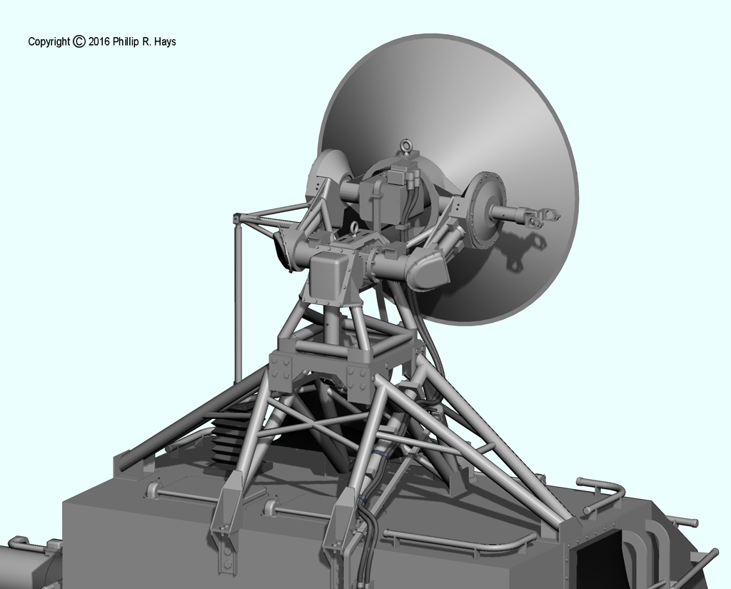
AN/SPG-49
Two SPG-49 missile tracking radar antennas were mounted on the after superstructure at about 77 and 92 feet above sea level. I worked from photos and sketches to create this model of the AN/SPG-49. During a visit to the USS Little Rock museum ship I took lots of pictures and I made some drawings with dimensions taken from the directors. The dimensions of this model should be accurate to within a few percent.
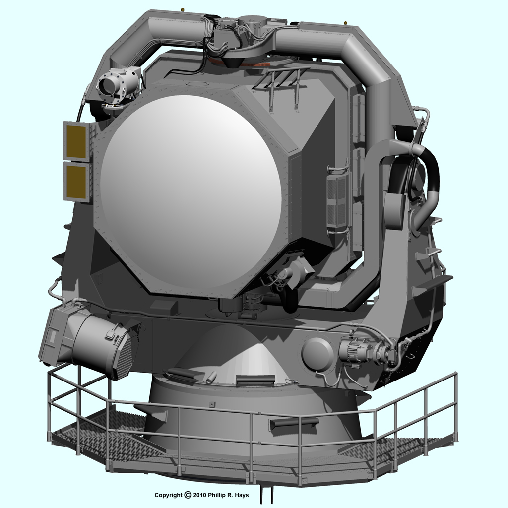
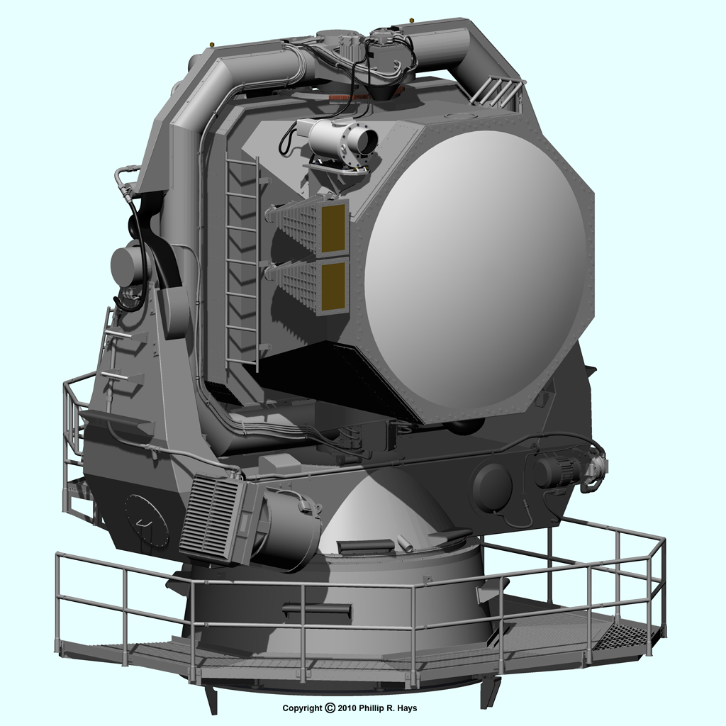
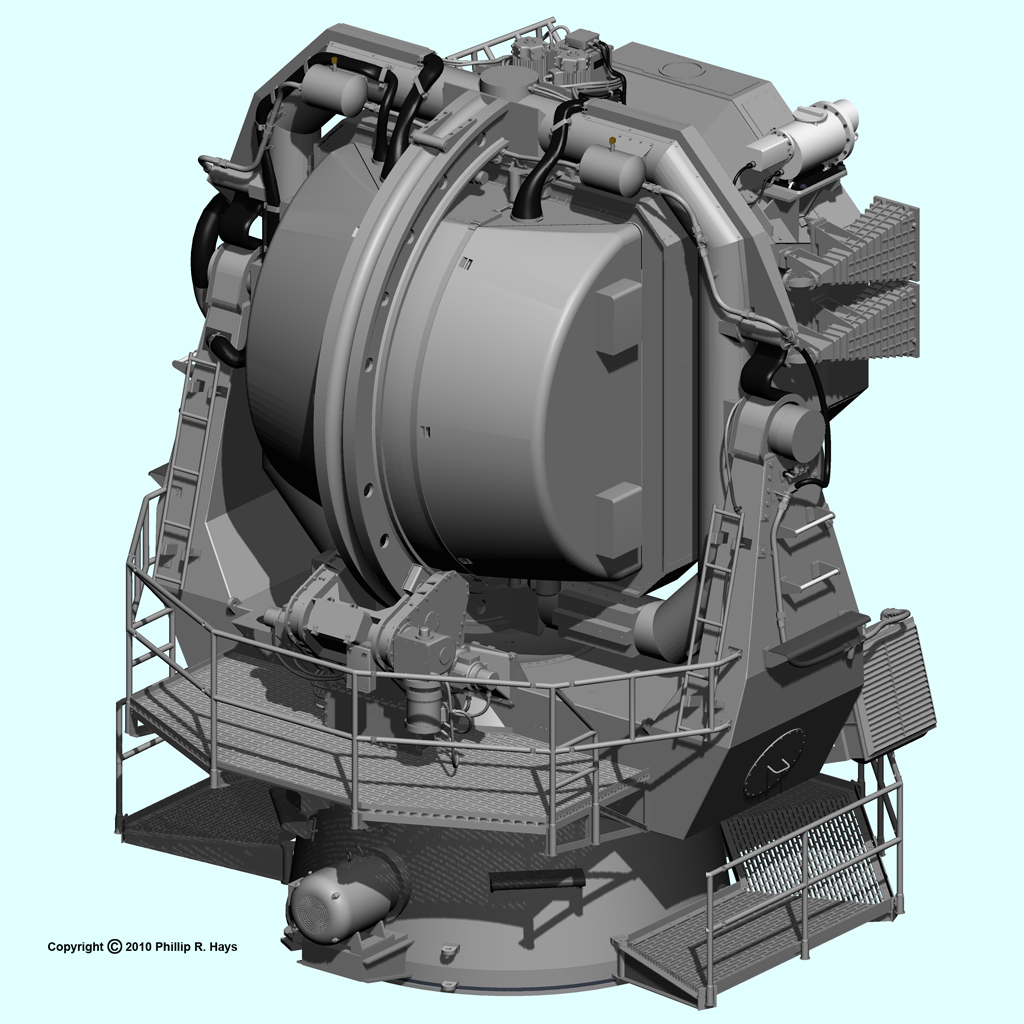
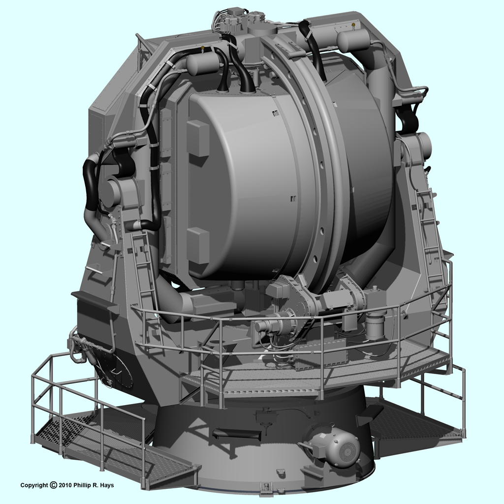
This thing was a monster by any definition. It was as tall as a two story house and gimballed to rotate around three axes. The 3 megawatt radar transmitters were located inside the antenna itself instead of inside the deck house as was common in other tracking antennas. The antenna was jammed full of electronic equipment, electric motors and hydraulic equipment. On top was a Mk12 television camera with a Mk7 telescopic lens for tracking targets visually.
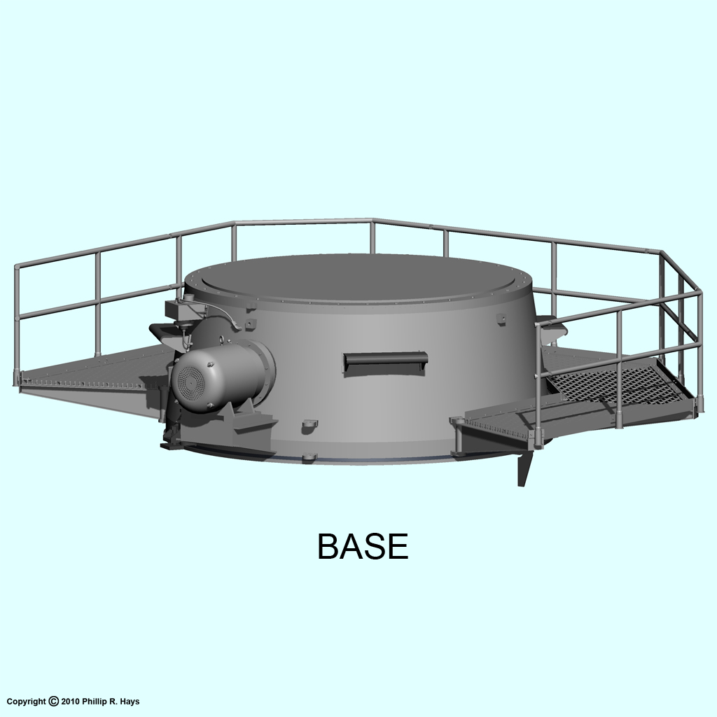
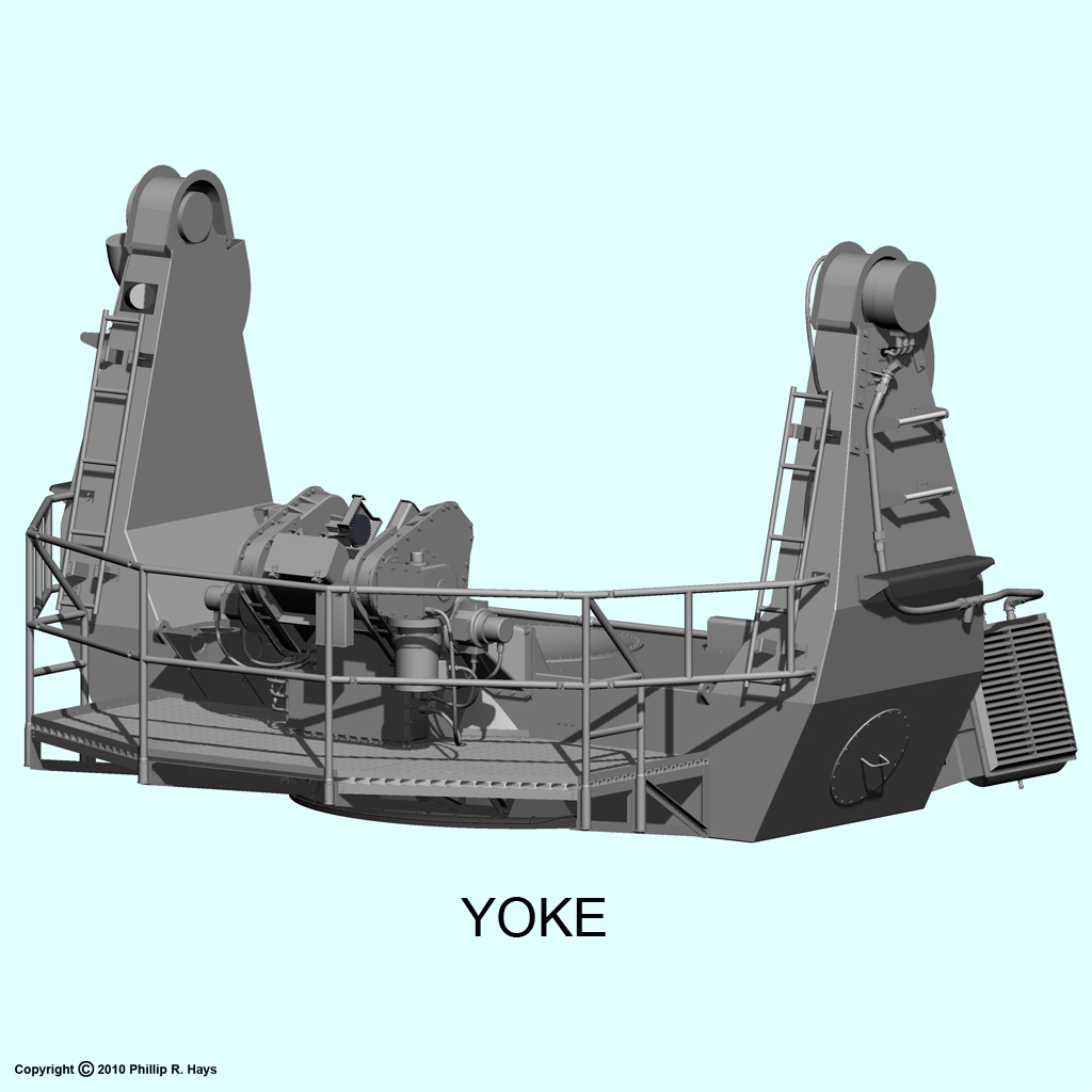
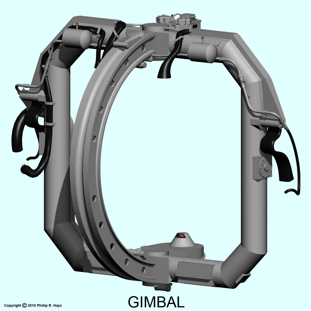
The entire antenna assembly rotated on the conical base around the vertical axis for coarse training in bearing. The square tubular gimbal rotated around the horizontal axis for training in elevation, supported by the "U" shaped yoke. The antenna itself rotated around the vertical relative to the gimbal for fine bearing adjustments.
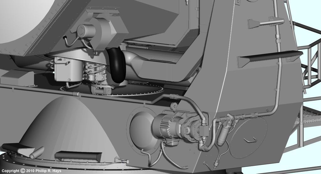
The large motor attached to the base turned the yoke. Two motor assemblies attached to the yoke at the rear drove the large "C" shaped gear on the gimbal. Four motors rotated the antenna, two on a platform at the top of the gimbal and another pair on a platform at the bottom. The antenna contained a cooling system with a pump to circulate the coolant and a large radiator with a fan to remove heat.
AN/SPW-2
Two AN/SPW-2 missile guidance transmitter antennas were mounted on the after superstructure at about 68 and 109 feet above sea level, one forward of the SPG-49s and the other aft. The model was based on photos of a unit on the USS Little Rock, plus several detailed and dimensioned sketches. It is a pretty accurate model.
The upper "U" frame rotated around the vertical axis on the cylindrical base. The antenna was mounted on an assembly that rotated around the horizontal axis, supported on the "U" frame. The feeder cone in the center of the antenna dish rotated 30 times per second. It rotated slightly off center to produce a conical beam. Behind the antenna reflector is a small optical telescope used for aligning the antenna. The telescope peeks through a hole in the reflector dish.
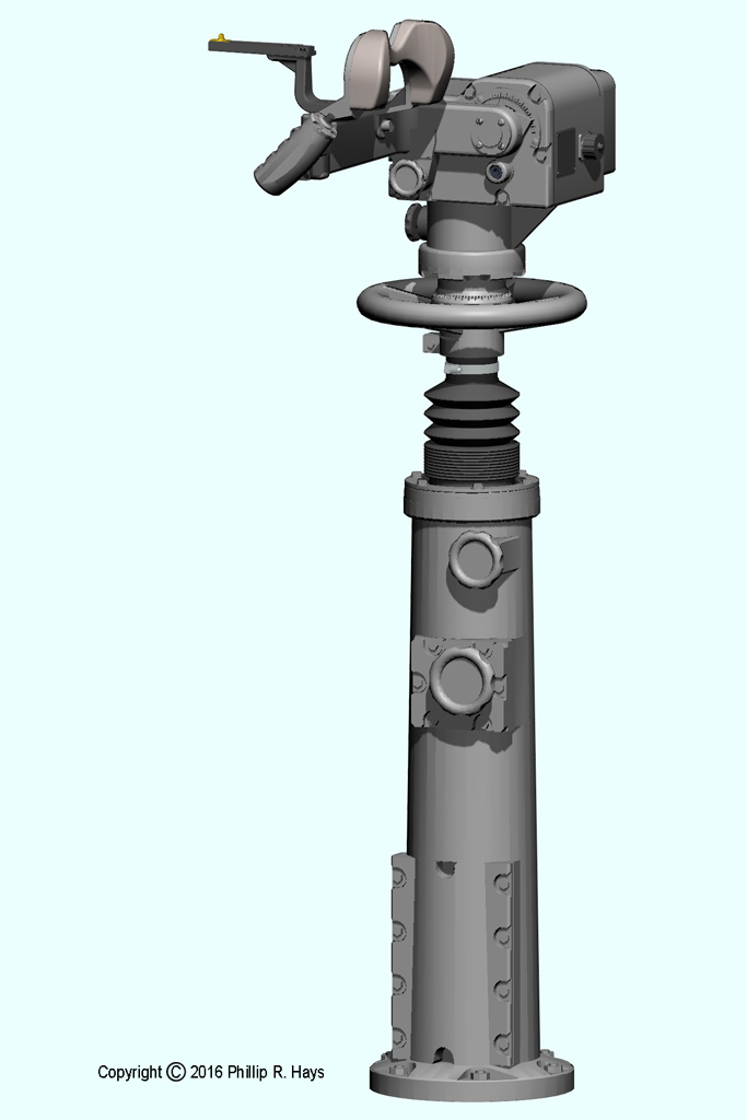
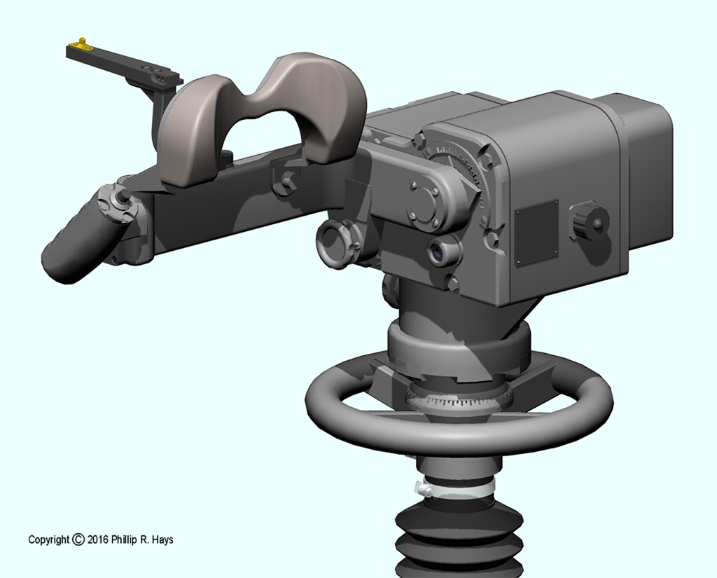
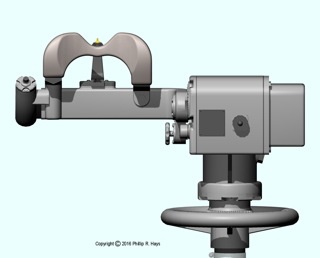
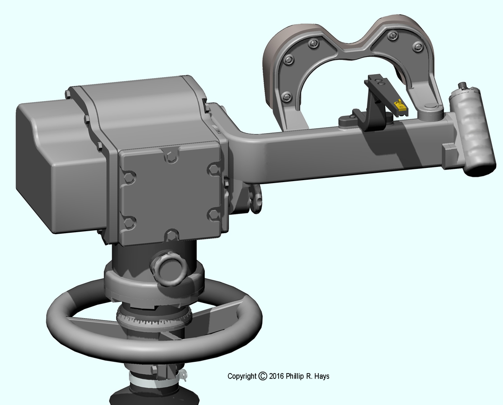
Mk 23 Mod 0 Target Designation Transmitter
The ship had two Target Designation Transmitters (TDT) on the O5 level, port and starboard, just forward of the Mk 37 director barbette. This was the Forward Air Defense station. These were relics from the WWII era, and were pretty much obsolete in the age of jet aircraft and missiles. I don't know if they were ever manned.
Binoculars were mounted on the TDT arm. The operator rotated the TDT about the vertical axis and raised the arm around the horizontal axis to place the target in the field of view. Then he pressed a button on the hand grip to send bearing and elevation data to the ship's gunfire control system. The gun control computer could then slew the Mk 37 director to the bearing and elevation to track the target.