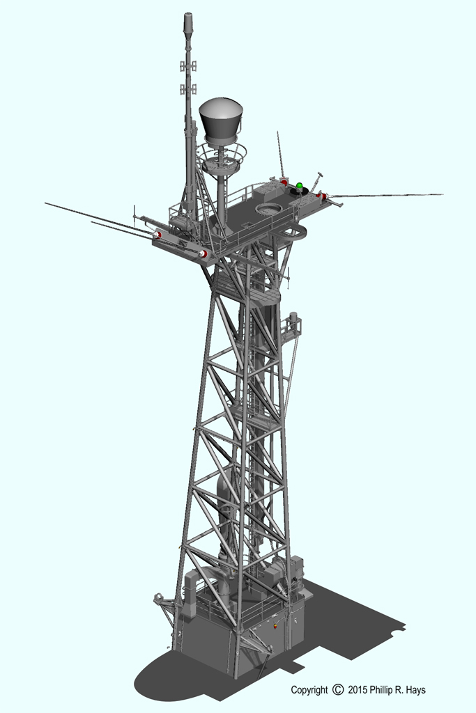
Forward Radar Tower
The forward radar tower was the most complex single part of the ship. It carried 49 antennas of various types and all the features necessary to support them. It was the first of my 3D models. I used it to determine the actual length of all the pipes. The blueprints were not clear about this - they showed the finished height of the vertical tubes, but these angled inward and are, therefore, longer than the overall height. The blueprints did not give the angles, so the lengths could not be calculated. In the shipyards they just welded together pieces, trimming them to fit as they went. That is what I did with the 3D model, and then I created detailed 2D drawings showing dimensions of all the pieces. The original towers were assembled complete with wiring and wave guides inside a building, and then moved to the ship for installation.
Note: elevations are given in feet and inches above the base line (ABL). The base line was the inside of the keel plates, 1 11/16" above the bottom of the keel. The bottom of the keel was about 21' 9" below the water line.
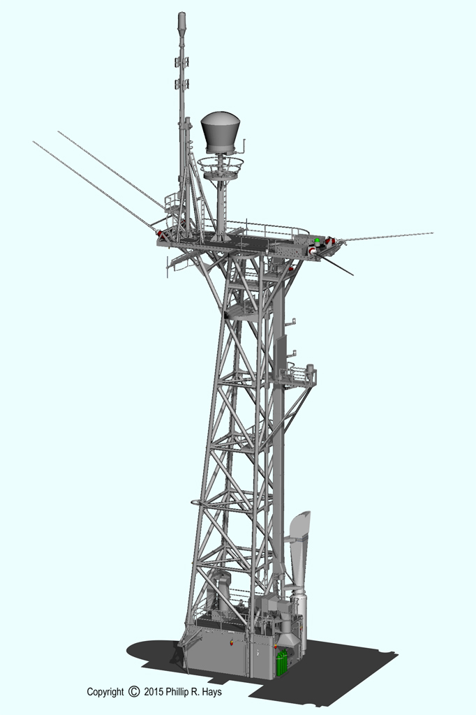
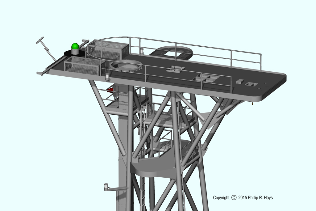
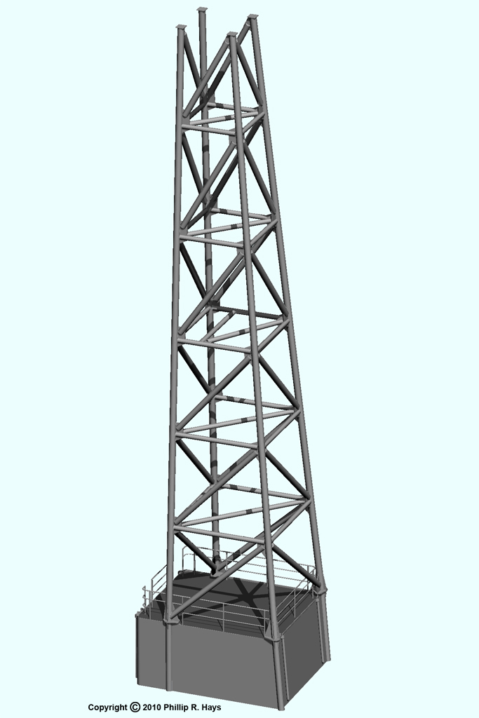
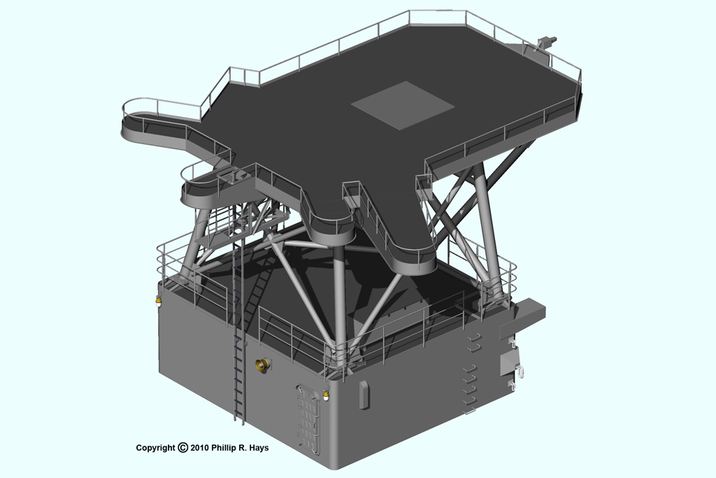
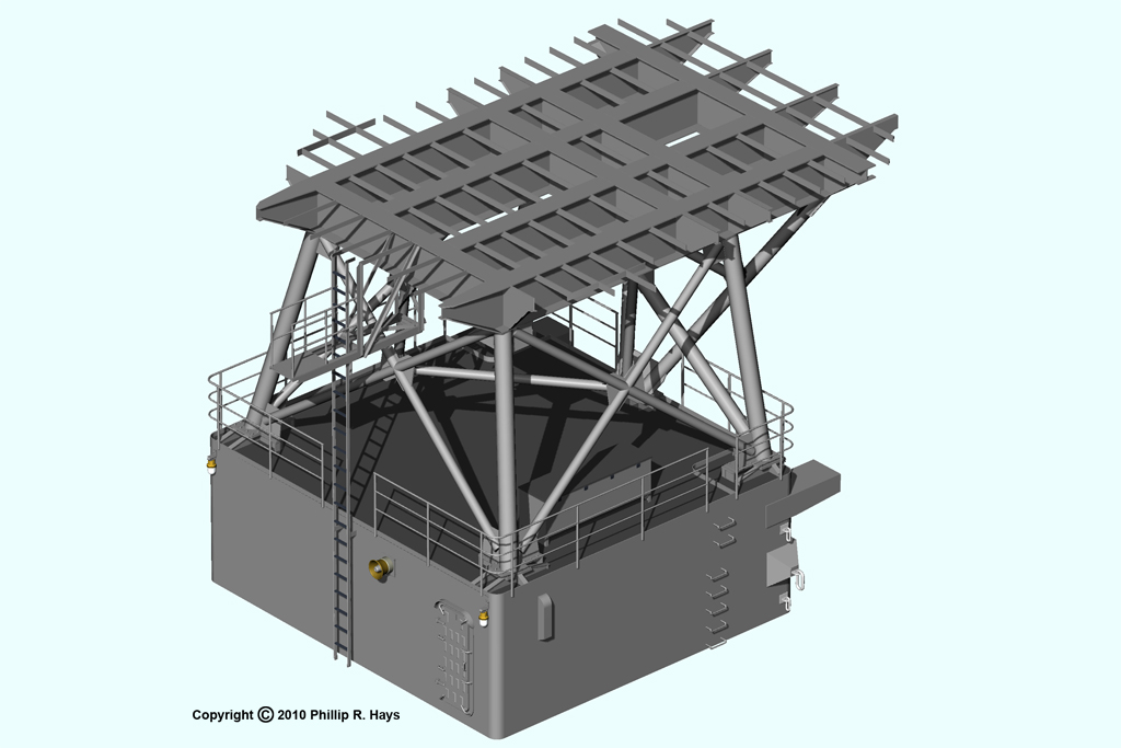
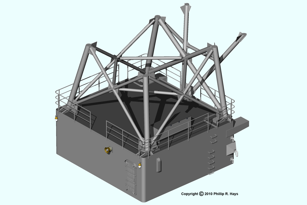
If you remove the antennas and spars, and then strip off the decks and support platforms the structure of the tower is easier to see. The basic structure is a free standing four tube lattice mast with horizontal and vertical diagonal bracing. The original 1959 design placed the tower on the O6 level (87'-4" ABL) on supports around the small Radio IV compartment on the O5 level (79'-7" ABL). In 1963 a small compartment was added at the O6 level between the diagonal supports, with platforms for electronics countermeasures (ECM) equipment outboard at the O6 level. Between 1967 and 1969 the large compartment shown here at the O6 level was constructed around the tower and the ECM antenna platforms were moved outboard. Note: the original construction had side diagonal braces (not shown here) at the lowest level.
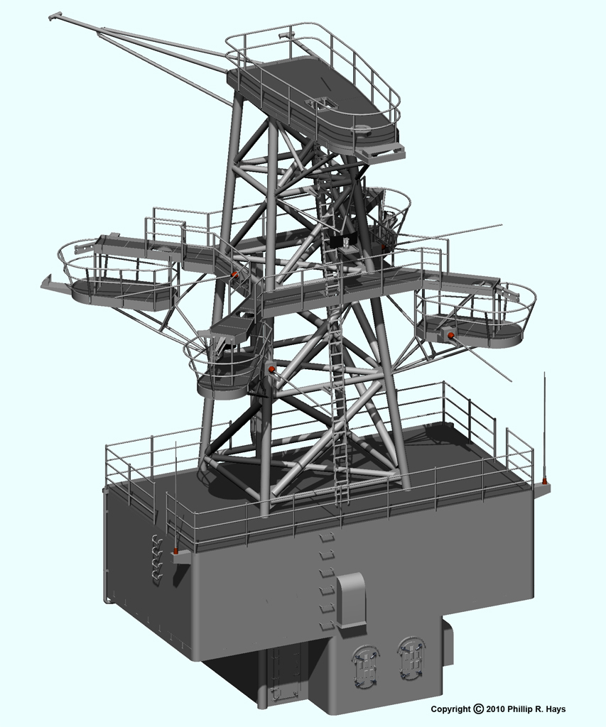
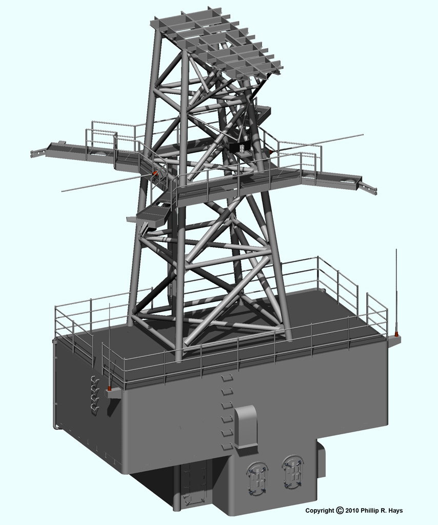

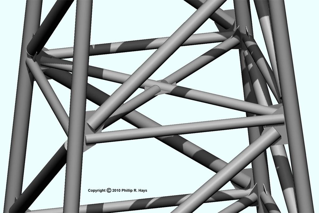
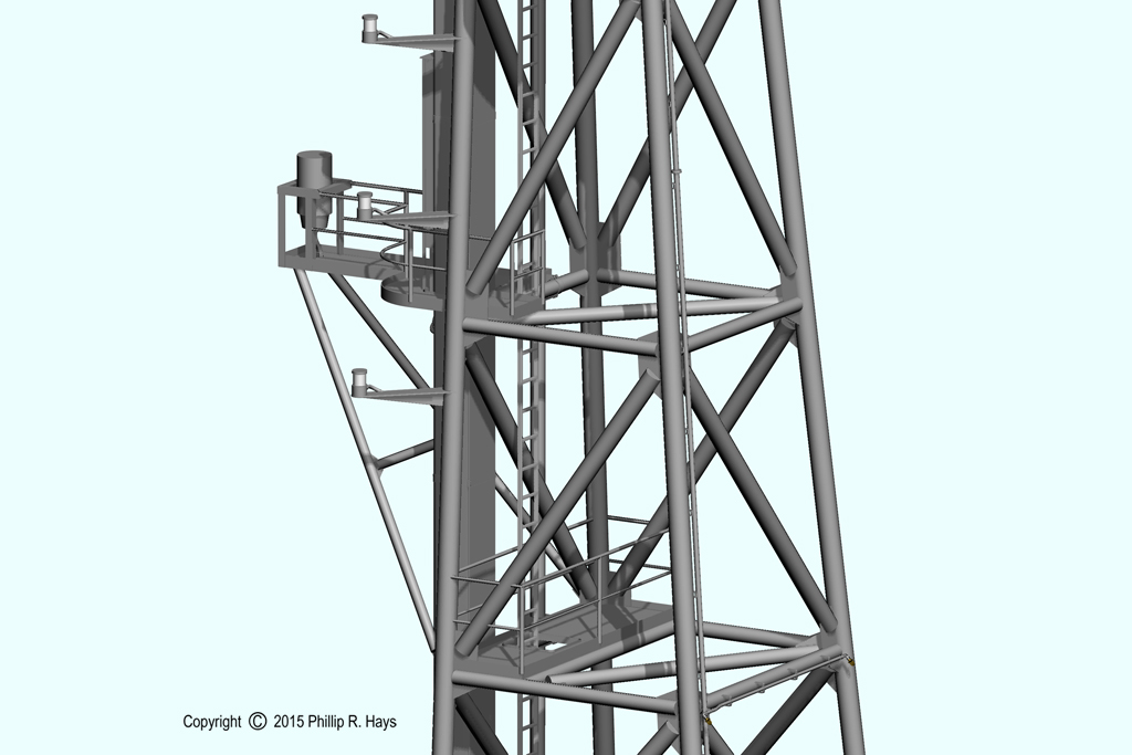
The tower was cross braced horizontally and vertically with support tubes. The ends of these tubes were split to fit over flat gusset plates welded to the vertical tubes. The "Z" bracing on the sides of the tower had horizontal and vertical diagonal support tubes welded to a common gusset plate. The internal "X" cross bracing had one tube diagonal across the tower, welded to gusset plates attached to the vertical tubes. This diagonal was slotted at the center to allow a gusset plate to pass through. Two short support tubes were welded to this center gusset and to gussets welded to the vertical tubes to complete the "X" cross bracing.
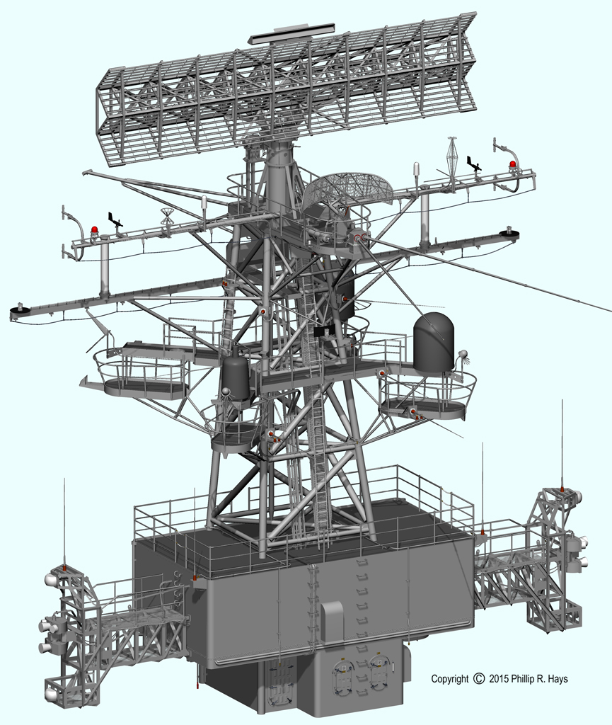
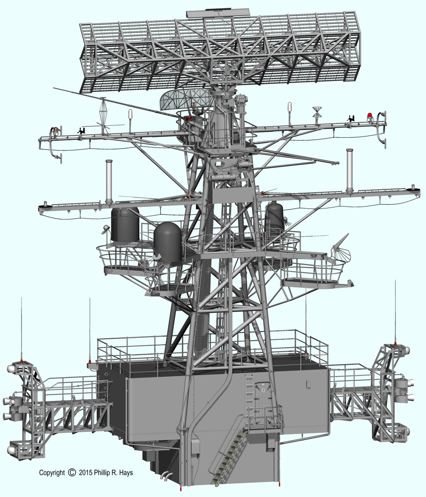
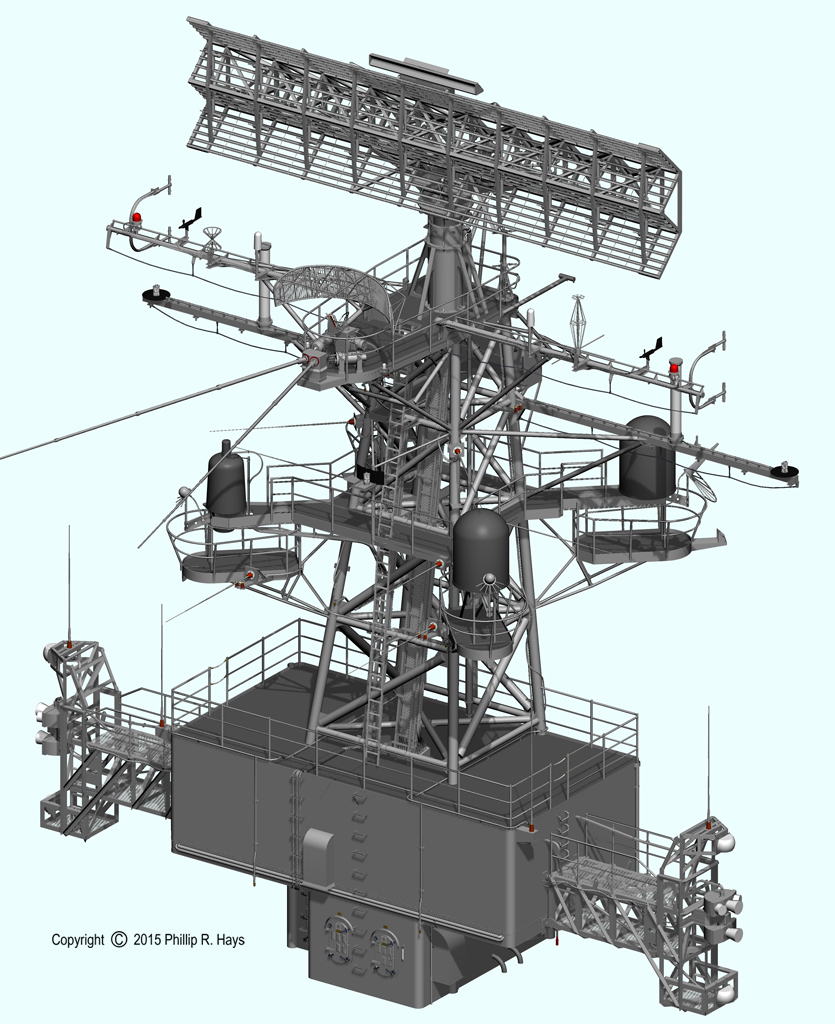
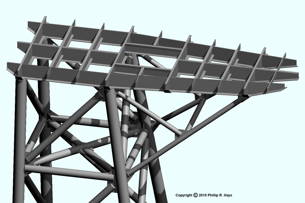
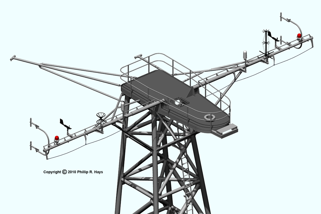
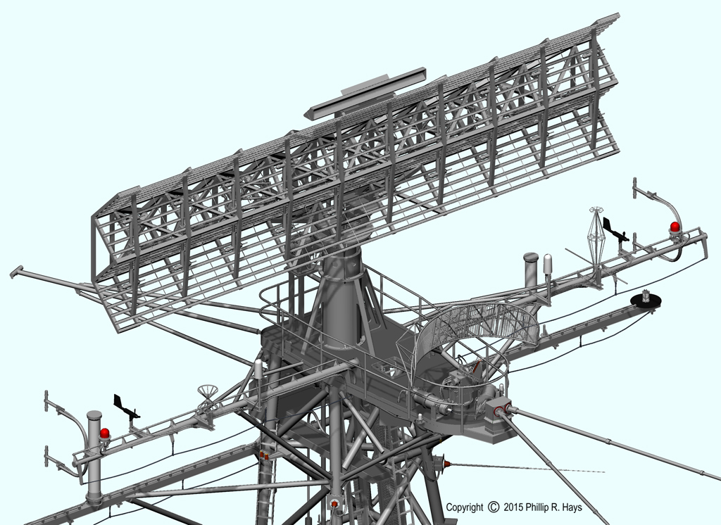
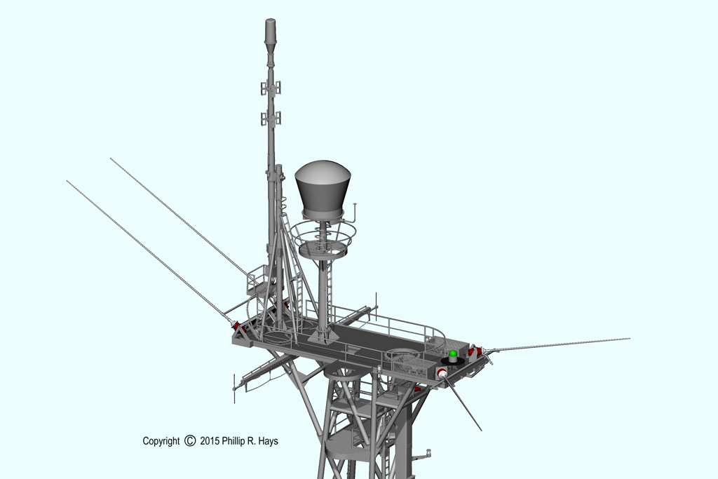
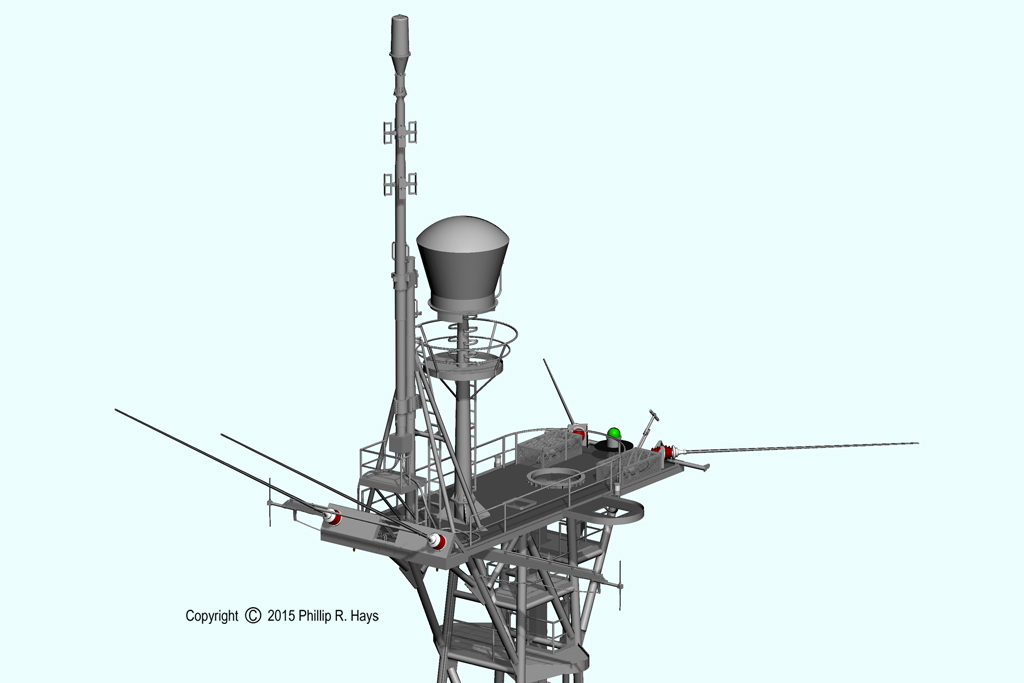
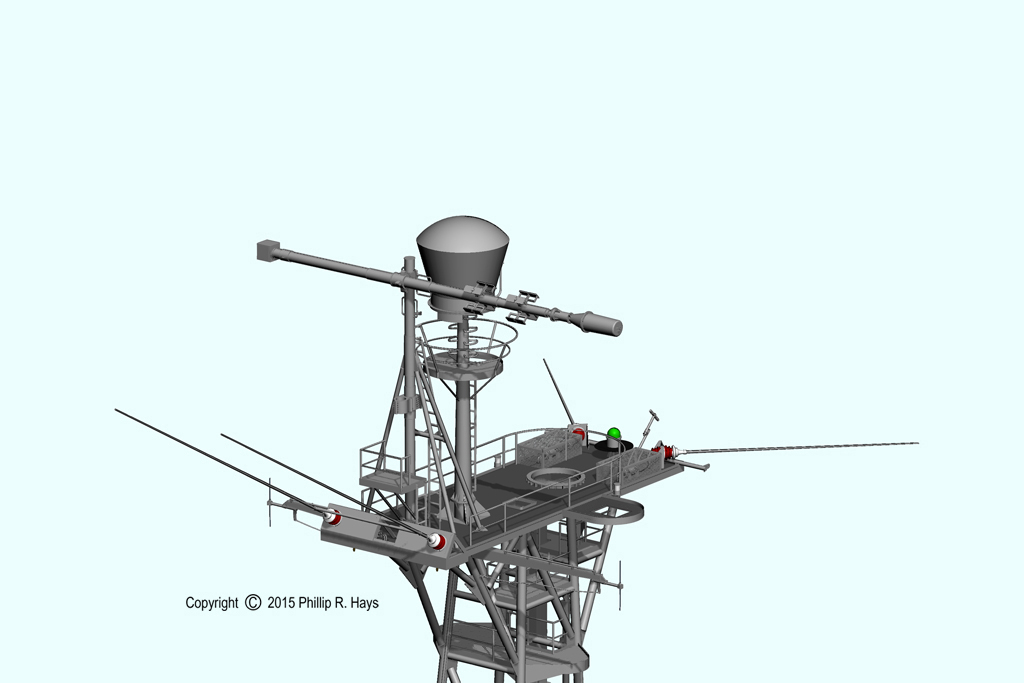
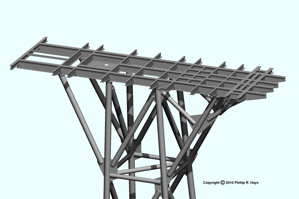
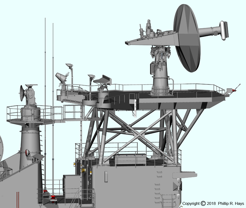
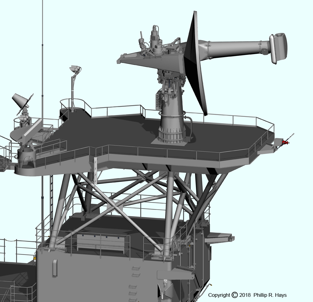
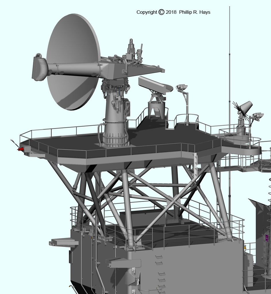
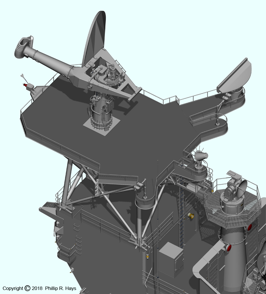
The top platform (128'-0" ABL) had an underlying structure of "I" beams to support the weight of the large AN/SPS-10 and AN/SPS-43 radar antennas. The platform was supported at the rear by the tower itself and by diagonal support braces under the forward part of the platform. A yardarm to either side carried a collection of antennas and wind speed sensors. A long battle gaff extended aft from the starboard rear corner of the platform, and a shorter gaff extended from the port rear corner. The ship's flag flew from the battle gaff at sea, and smaller pennants flew from the other gaff. The large "bedspring" antenna at the rear of the platform was the AN/SPS-43 long range air search radar antenna. The shorter bar antenna attached to the top was an IFF (Identification Friend or Foe) interrogator antenna. The ship carried a smaller AN/SPS-37 air search antenna in 1960, but this was replaced with the SPS-43 in 1963. The smaller parabolic antenna at the front of the platform was the AN/SPS-10 surface search radar.
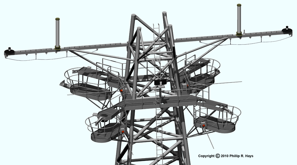
Half way up the tower (113'-0" ABL) was an "X" shaped platform that was called the "cloverleaf." It supported a collection of electronics countermeasures (ECM) antennas, some under the large black dome covers. Platforms suspended below the cloverleaf (109'-0" ABL) provided access to service the antennas. Just above the cloverleaf was a signal halyard spar (120'-6" ABL). This was originally placed at the cloverleaf level, but was moved up to the position shown here between 1967 and 1970. The Range Light was mounted above the forward edge of the platform 117'-11 1/2" ABL.
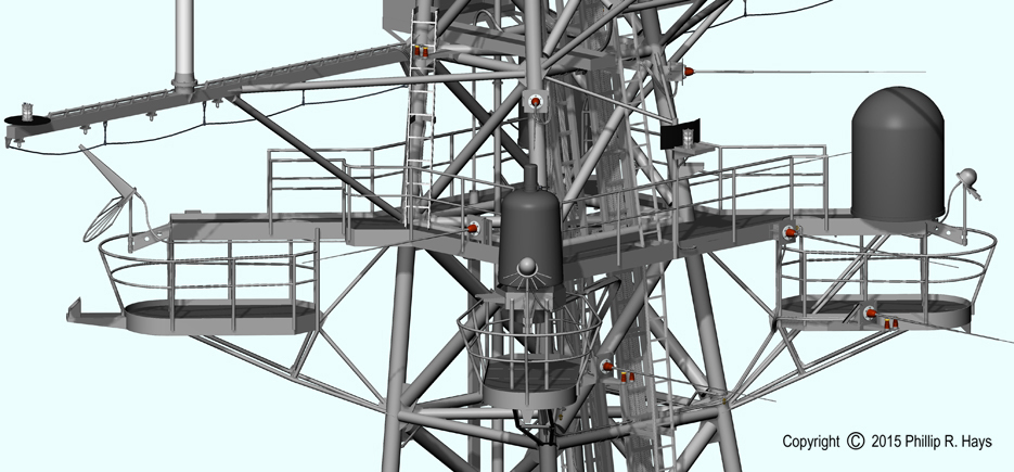

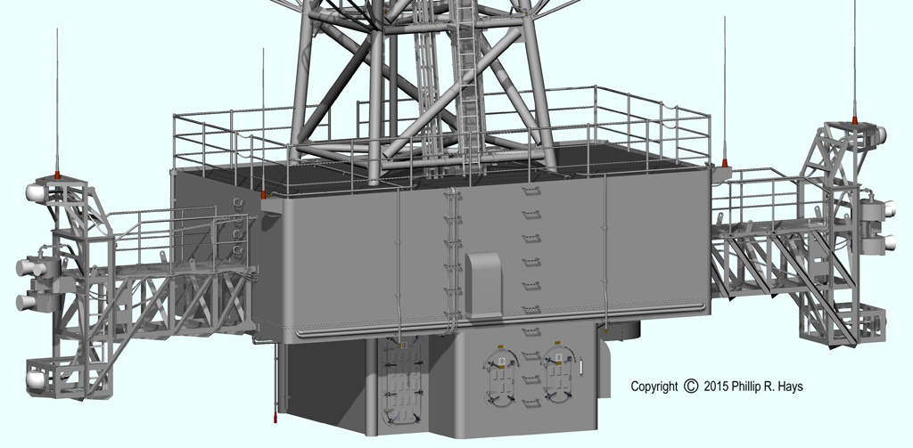
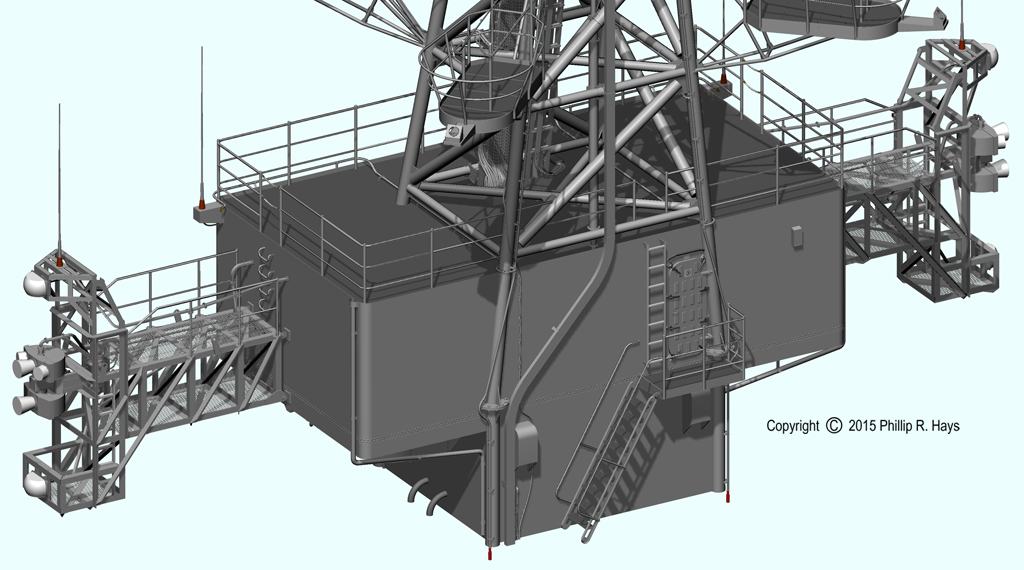
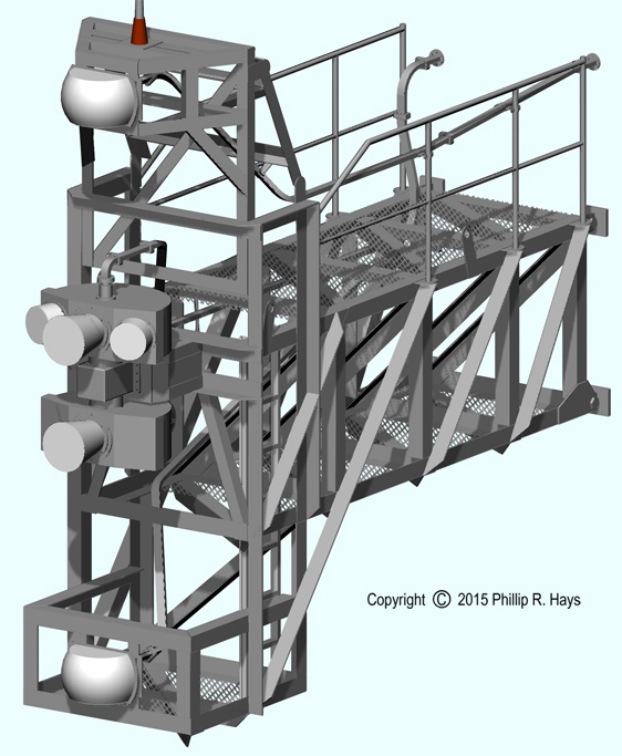
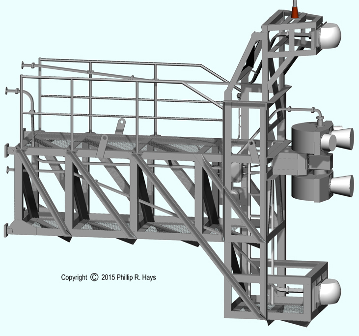
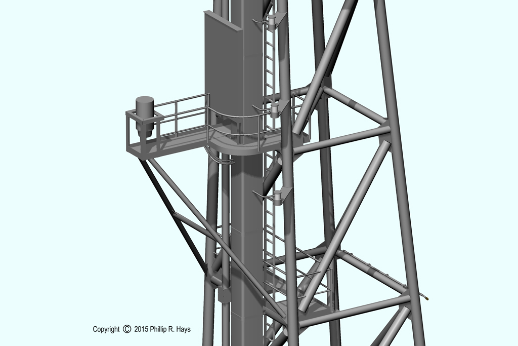
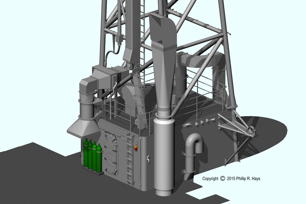
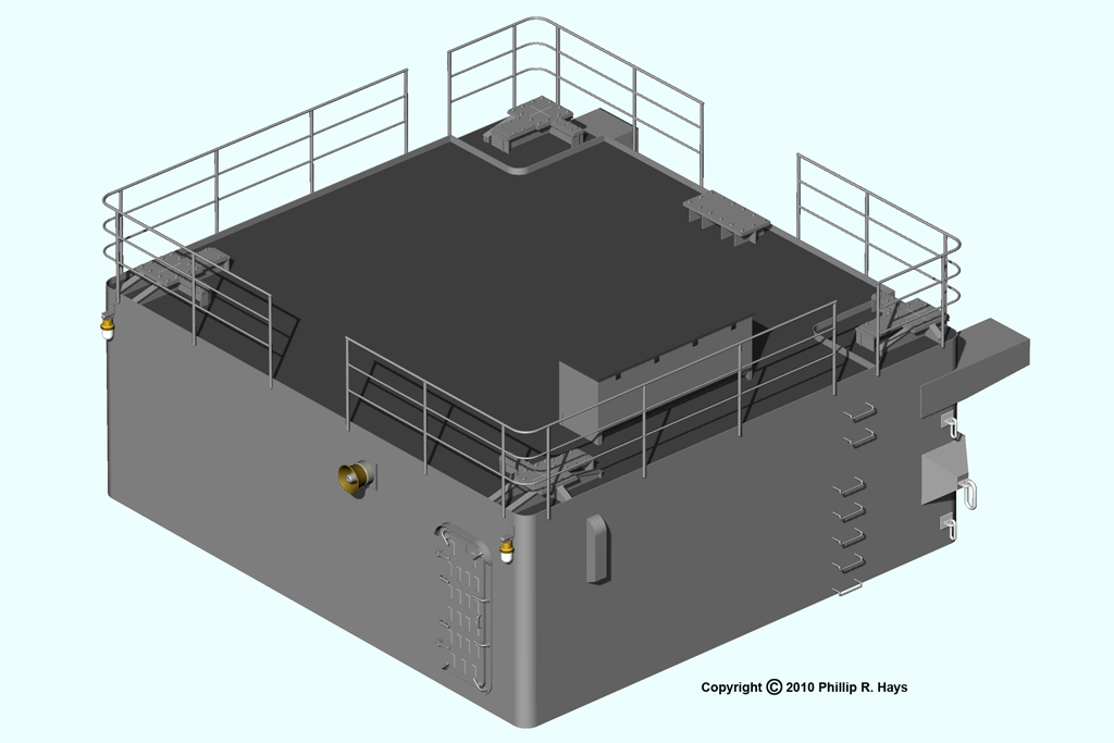
The large compartment at the base of the tower (O6 level) contained a suite of ECM equipment to detect enemy radio and radar transmissions. The equipment could also detect approaching missiles and generate countermeasures signals to confuse the missiles and send them off course away from the ship. The platforms to either side carried some of the ECM antennas. The O6 level ECM compartment rested on the smaller O5 level Radio IV compartment.
Midship Radar Tower
The midship radar tower originally carried several large antennas on the platforms at the top. However, the ship was dangerously top heavy so some of the antennas were eliminated and others were moved to lower positions on the forward tower. The remaining antenna were TACAN, communications and other functions.
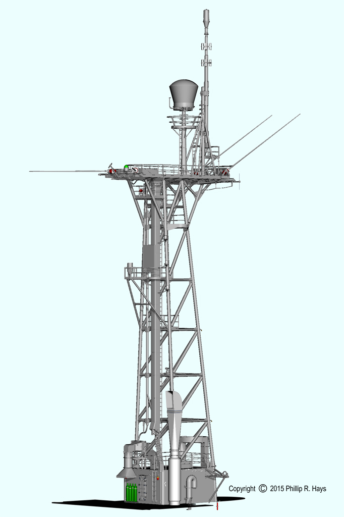
The Tactical Air Navigation (TACAN) system (inside the large cover) broadcast a signal that could be used by aircraft to determine the range and bearing to the ship. It was used primarily by helicopters bringing mail and supplies to the ship, and the Admiral's helo. It could also be used by ships to facilitate rendezvous.
At the forward edge of the upper platform was a stub mast with an AN/URD-4 radio direction finder antenna at the top that was used to find bearings for search and rescue operations. The mast was hinged at a point just forward of the TACAN antenna cover. This allowed the mast to be swung down and to the side so the ship could pass under low bridges. One of the shipyards where the CLG conversions were done was just upstream of a bridge that was a bit too low for the ships to pass under unless the mast was rotated to the side.

Originally the top platform's rear edge was curved, following the curve of the hand rails. Later the platform was extended to allow more antennas to be installed. The large circular foundation aft of center originally held a AN/SPS-39 3D air search antenna. This was removed in 1967 as a weight saving measure. The platform's support structure was a grid of heavy "I" beams to support the weight of the original antennas and masts. This framework was supported fore and aft with diagonal braces. The "D" shaped platform on the port side originally supported an antenna that had been removed.
Below the top platform (144'-0" ABL) were a series of smaller platforms at 139'-0" ABL, 137'-0" ABL and 132'-1" ABL that originally provided support for and access to antennas. About half way up the tower were two additional platforms at 119'-4" ABL and 107'-4" ABL. The lower platform was part of the original CLG conversion, but the platform at 119'-4" ABL was added in 1967. I have no idea what the cylindrical thing was that was mounted on the platform or what purpose was served by the vertical panel. The large rectangular cross section vertical tube and the smaller pipe beside it enclosed cables.
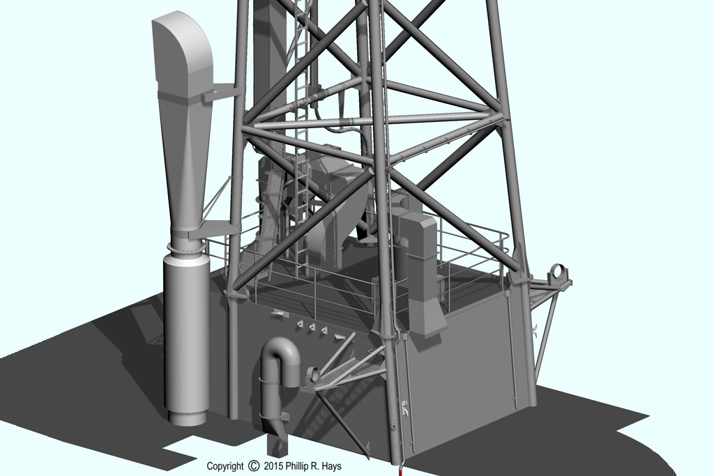
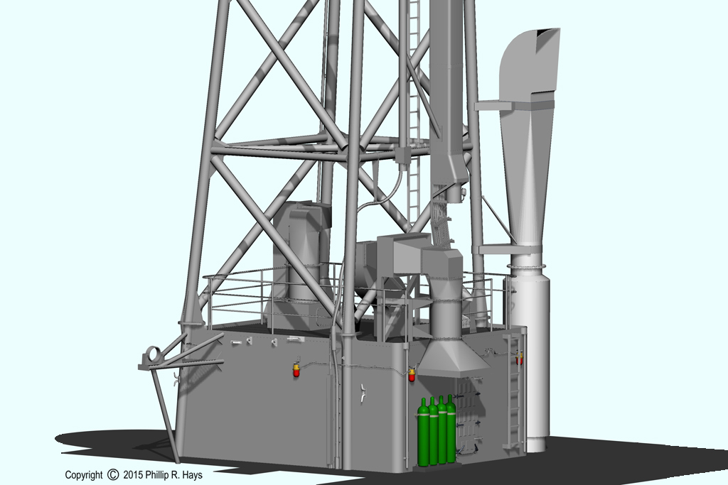
The main tower structure was a freestanding four tube lattice assembly. At the base of the tower was the Radar V control room on the O3 level (65'-3" ABL). The tower bolted to plates (73'-3" ABL) atop tubes built into the deck house sides. Large vent fans on the O4 level moved cooling air in and hot air out of this space. The air intake had steam heating and air conditioning units to allow the temperature of the incoming air to be controlled. The large stack on the starboard side went through a series of variations. This is the 1971 configuration. I think this was the galley stack, but I have not traced the ducts to the spaces below.
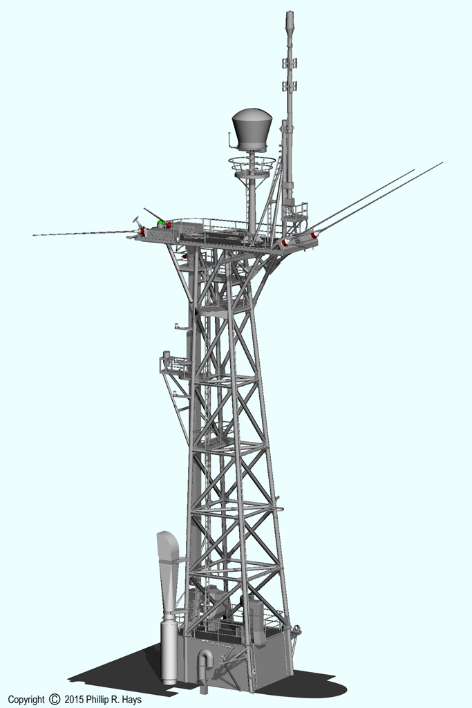
Aft Radar Tower
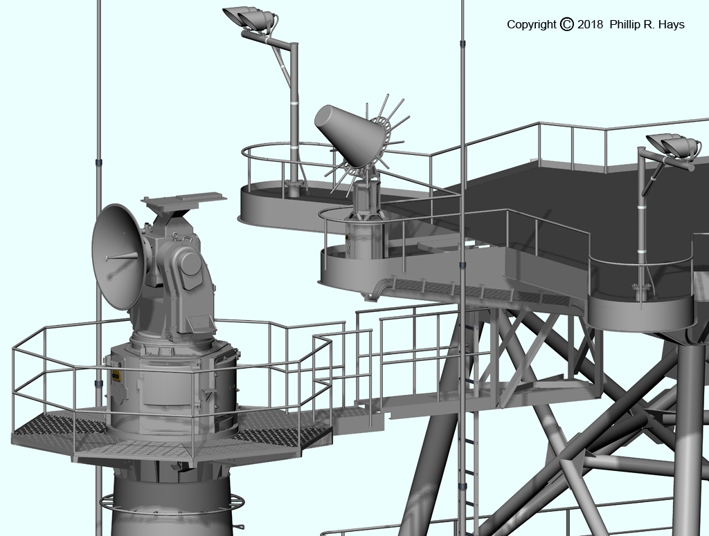
The after tower carried the AN/SPS-30 air search and height finding radar, an AS-791/UPA-43 IFF Interrogator antenna slaved to the SPS-30, plus a collection of communications antennas and telemetry antennas. Originally the tower carried a AN/SPS-8B height finding radar antenna, which was replaced in 1963 with the SPS-30.
There was a great deal of variation in the construction of this tower and platform between the USS Galveston CLG-3, USS Little Rock CLG-4 and the USS Oklahoma City CLG-5. This is the OK City configuration. The greatest differences were in the locations of the smaller platform extensions. No two ships were alike, although the AS-979A/UKR telemetry antenna (the cone with the array of rods) and the platform it was on were located at the same position on all three ships.
The top platform (103'-0" ABL) had a massive "I" beam support to carry the weight of the large radar antenna. With the platforms removed the structure of the tubes and braces can be seen. It was built the same way as the other two towers. The four vertical tubes and the front angle supports rested on footings on the top of the after deck house above the missile house. These footings were at the O5 level (88'-1" ABL) above the Radar VII compartment on the O4 level (80'-1" ABL).
The ship originally had an after steering station on the O4 level just aft of Radar VII and forward of the SPW-2 tower. A binnacle was located on the O5 level near the vertical ladder. This equipment had been removed before 1971.
A smaller platform (98'-0 3/4" ABL) hanging below the top platform provided access to an AN/SPW-2 missile guidance antenna platform immediately aft. The two platforms did not actually connect to each other. The gap between the two structures prevented strain buildup in the towers when the ship flexed in heavy seas.