
Distilling Plant
The ship required a large amount of fresh water for boiler feed, cooking, drinking, bathing and washing. Storage tanks could hold only a few days' supply, so a distilling plant operated almost continuously to provide pure water. The ship had two 20,000 gallon per day primary distillation units in the evaporator room above the forward engine room between the uptakes. A 12,000 gallon per day auxiliary distillation unit was located in the after engine room. Up to 52,000 gallons of fresh water could be produced each day.
The distillation plant boiled sea water and condensed the vapor to produce fresh water (distillate). Sea water contains dissolved minerals, salts and microorganisms that must be removed, and they are left behind in the brine after water vapor has boiled off. This brine is discharged overboard back into the sea. The distillate is used for boiler feed water, and it is essential that the concentration of salts and minerals be very low or they will form deposits in the boiler tubes. Such deposits absorb heat and cause hot spots that eventually melt the tubes and cause tube failure. Fresh water from the distilling plant contains only traces of the chemicals and biological contaminates in sea water, but it is not totally pure. Special procedures were necessary when the ship was operating in heavily contaminated waters and in harbors.
These units took in cool sea water and transferred heat from the auxiliary steam supply to the water to boil it. Auxiliary steam was heated to 490°F, quite a bit above the 212°F boiling temperature of water at atmospheric pressure. The distillation units were operated at near vacuum, and the lower pressure meant that the water boiled at a lower temperature, making the condensers operate more efficiently than they would at higher temperatures and pressures. Lower temperature operation also meant less heat was discharged overboard with the cooling water for the condensers.
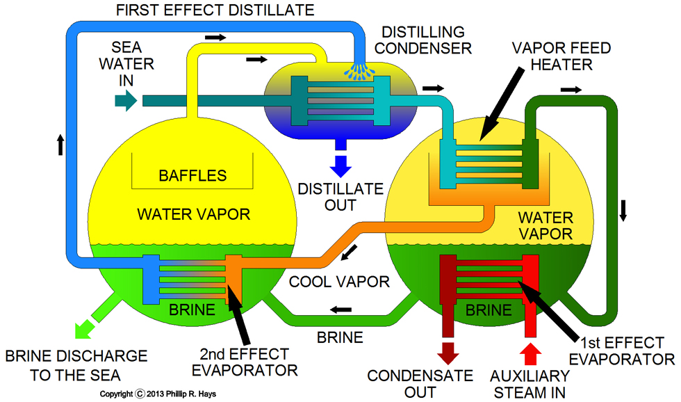
The primary distilling plant had two-shell double effect low pressure distilling units. Two of these were installed in the evaporator room. One of these two-shell units is shown in the diagram above. Cool sea water was pumped through the distilling condenser where it picked up heat from the hot water vapor coming from the second effect evaporator. Then it passed through the vapor feed heater where it gained more heat from the hot vapor in the first effect evaporator. This preheating of the sea water recovered some of the heat in the system while using the cool sea water to condense the distilled water vapor from the evaporators.
Then the warm sea water brine flowed into the bottom of the first effect evaporator where it was heated to boiling by auxiliary steam from the ship's boilers. The cooler sea water condensed the auxiliary steam and the condensate was returned to the boiler feed water system. The hot brine from the first effect evaporator flowed into the second effect evaporator where it was boiled again by heat in the vapor from the first effect evaporator. The secondary effect evaporator was under lower pressure than the first effect evaporator, and this pulled the brine into the secondary effect evaporator. The hot salty brine remaining after boiling in the second effect evaporator was discharged into the sea.
Hot water vapor in the first effect evaporator rose through baffles and a vapor separator to the top of the drum. The vapor contained small droplets of brine. The baffles collected these drops and drained them back into the brine at the bottom of the drum. The vapor entered the vapor feed heater where it lost heat to the incoming sea water, but it did not cool enough to condense. From there the cooler water vapor flowed into the second effect evaporator. Because of the low pressure in this drum the vapor was still hot enough to boil the brine. As the vapor lost heat to the brine it condensed, creating a vacuum that pulled the vapor from the first effect evaporator into the second effect evaporator. The condensed first effect distillate was then pumped to the distilling condenser.
Vapor from the boiling brine in the second effect evaporator passed through baffles to remove brine droplets and then out the top of the second effect evaporator to the distilling condenser. There the vapor lost heat to the incoming sea water in the condenser and condensed into distillate. Cool distillate water from the first effect evaporator was sprayed into the distillate condenser to enhance the condensation of the vapor from the second effect evaporator. As the vapor condensed it created a vacuum that served to draw vapor from the second effect evaporator. The condensate from the distillate condenser was the final fresh water for boiler feed, drinking water, and other uses.
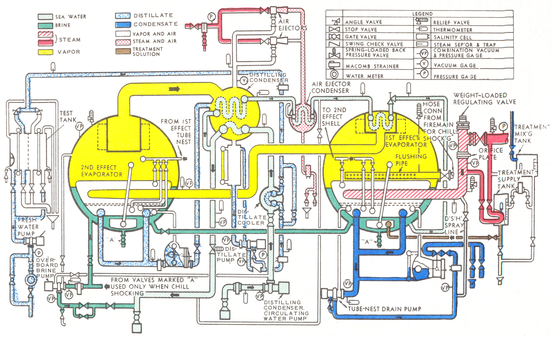
The diagram above is greatly simplified from the actual operation of the distilling unit. The diagram at the right shows all of the pumps, valves, gauges, deaerating units and other equipment used with the two shell distilling plant. During operation mineral deposits called "scale" could form in the unit, and this interfered with heat transfer and reduced efficiency. One method of dealing with scale buildup was to introduce chemicals that would interfere with scale formation. This wasn't totally effective, and occasionally it was necessary to use "chill shocking" to break loose scale. For this the unit was secured and pumped dry while still hot. Then cold sea water was introduced, creating thermal shock, causing the scale to break loose and settle to the bottom of the drum. Distilled water output was controlled by regulating the auxiliary steam input pressure to the first effect evaporator. When the steam pressure was reduced the steam became superheated. Superheated steam increased the rate of scale formation in the evaporators, so it must be de-superheated before it was used. The final distillate output collected in a test tank where the chemical content could be checked. From there it was pumped to the ship's fresh water systems.
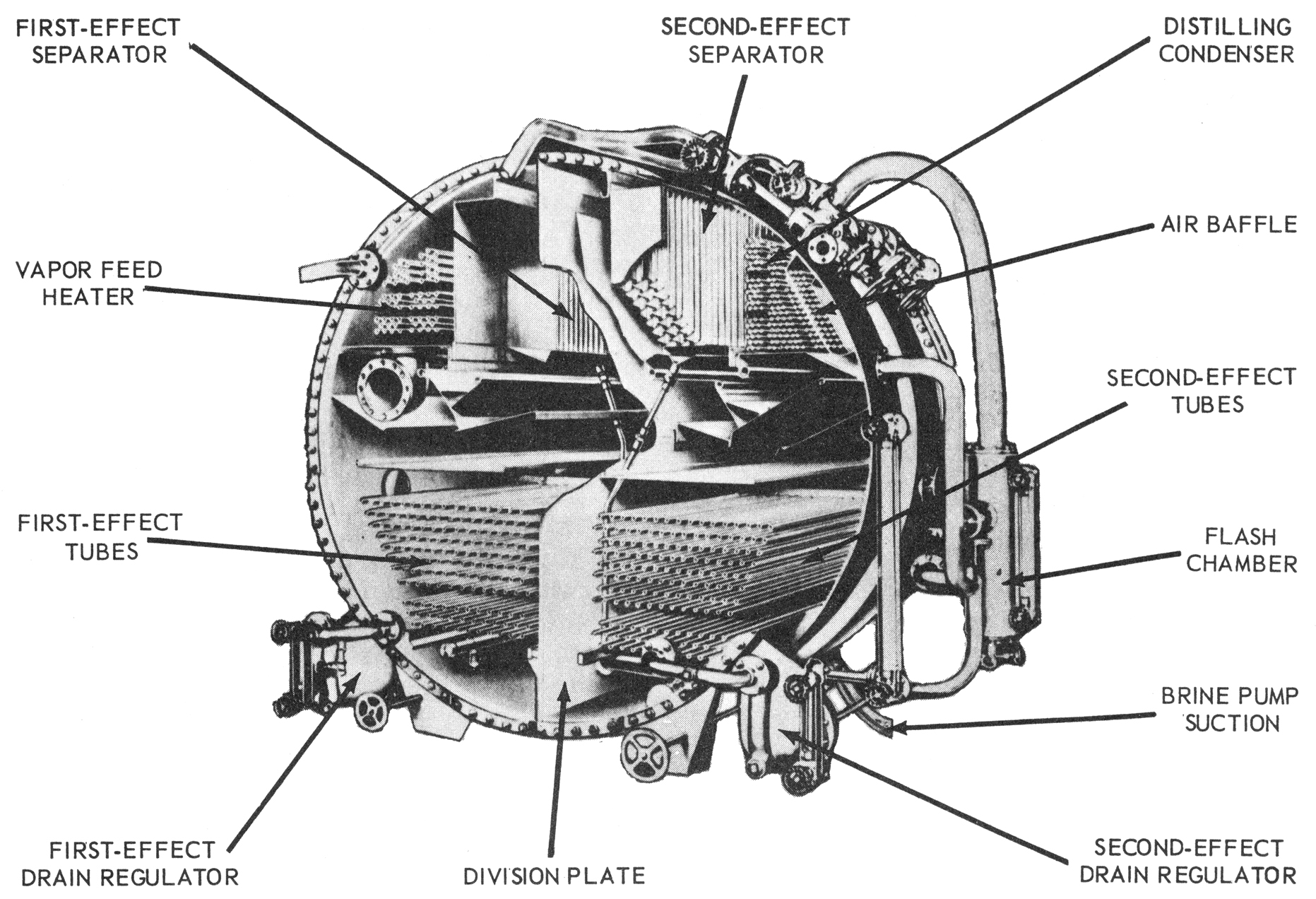
The auxiliary distillation plant in after engine room used a single 12,000 gallon per day soloshell double effect unit. The cutaway diagram shows the structure of these distillation plants. All evaporator elements were contained in a single shell. A partition down the middle of the drum separated the first effect and second effect evaporators. The distilling condenser was located inside the shell in the second effect side. Operation was very similar to the two shell plant described above.
It was important to maintain steady operating conditions for the distilling plants. Changes of pressure and temperature could cause increased carryover of brine to the distillate, increasing salinity of the fresh water. The designed vacuum was necessary for efficient operation. If the vacuum was less the unit operated hotter and scale formation increased. Brine concentration was also important - if it was too low less fresh water was produced, and if it was too high scale formation would increase.
Generators
The primary electrical power generating units were four steam powered turbo generators. Two were located in the forward fire room and two in the after fire room. The original Cleveland class ships had 600 kilowatt turbo generators. These were upgraded to 750 kilowatt generators on the Talos CLGs to provide power for the missile tracking radars. These generators were driven by superheated steam from the boilers. Below the turbo generators were the auxiliary condensers to convert steam back into feed water and produce the vacuum necessary for the turbines to function.
The ship had two 250 kilowatt diesel generators, one in the forward engine room and the other in a diesel generator room just aft of the after engine room. These were auxiliary generators that could be used when the boilers were not producing steam. Two additional 60 kilowatt casualty power diesel generators were added for the CLGs on the lower decks forward and aft of the main engineering spaces. These could be used to power emergency equipment in case of major damage in the engineering spaces. Two 75 kilowatt motor generators were located one each in the forward and after fire rooms. These had large AC (alternating current) electric motors to turn the generators to produce DC (direct current) electricity for equipment that needed it.
Each pair of 750 kilowatt turbo generators had an associated switchboard that allowed electrical power to be distributed from each generator to electrical circuits throughout the ship. Normally one switchboard would provide power to the entire ship with the other switchboard and generators in standby mode. The switchboards also allowed damaged circuits to be disconnected from ship's power for repairs. Additional generators could be brought on line when power demand increased. For example, an additional turbo generator might have to be brought on line when the 3 megawatt Talos AN/SPG-49 missile tracking radars were powered up.
Each 250 kilowatt auxiliary generator had a switchboard to allow electricity to be supplied to different systems throughout the ship. If the primary switchboard suffered a casualty the auxiliary generators would start up to supply power until the load was switched to the other primary switchboard.
Steering Gear
The steering gear on the OK City was of the electrohydraulic type. In this type of system a constant speed electric motor drives a hydraulic pump to generate pressurized hydraulic fluid. The hydraulic fluid drives hydraulic cylinders or "rams" that actuate the rudder mechanism. The advantage of this arrangement is that large changes in rudder angle do not create sudden varying loads on the electric motor.
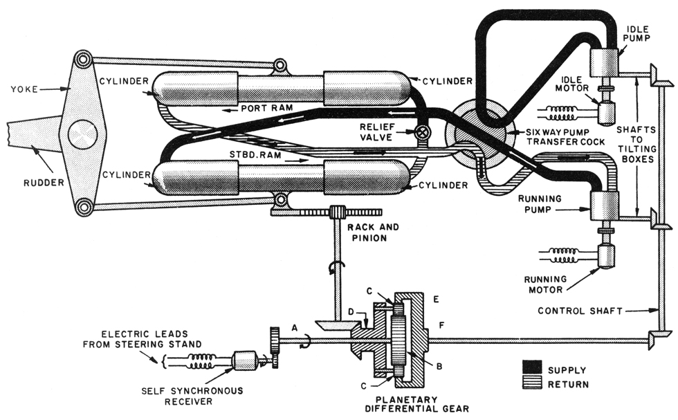
The diagram shows a typical double-ram electrohydraulic steering gear in cruiser installations. Some cruisers had a similar installation with the ram cylinders located beside the rudder stock, with the cylinders connected directly to the double yoke on the stock. The system shown has two pumps, one running and the other idle, to provide redundancy in case one motor stops working. The pump transfer cock allowed one or the other pump to be connected to drive the cylinders.
The volume of hydraulic fluid and direction of flow were determined by a tilting block mechanism in the pump. This was controlled by a signal to the servo receiver from the steering station. The receiver drove a gear train that adjusted the angle of the tilt block in the pump. A change in position of the steering wheel caused the pump to push hydraulic fluid under pressure into the hydraulic rams. The cross connected fluid feed to the rams caused one to push forward and the other to push aft, turning the rudder yoke. Linear movement of the rams also drove a rack and pinion gear that drove a rotary shaft with another gear that adjusted a planetary gear system. This rudder position feedback returned the pump control to the neutral position when the desired rudder angle was achieved. This adjusted the tilting blocks in the pump so no fluid flowed to or from the rams. The rams were then held in position by the static hydraulic pressure in the connecting pipes.
The ship also had an emergency steering system in the steering gear compartment. It used a hand operated pump with valves to isolate the main hydraulic pumps while the hand pump was being used. Normally the hand pump was isolated from the hydraulic system. Steering orders were passed by verbal communication from the steering control station to the after steering compartment. The Oklahoma City originally had two steering control stations, one in the pilot house and another "after control" station in the aft part of the superstructure. If the pilot house was damaged the ship could be conned from the after control station. With the CLG conversion the aft control station was placed on top of the aft deck house beneath the after radar tower.
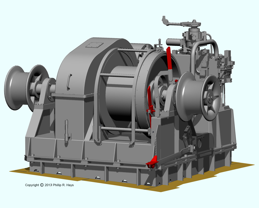
Anchor Handling
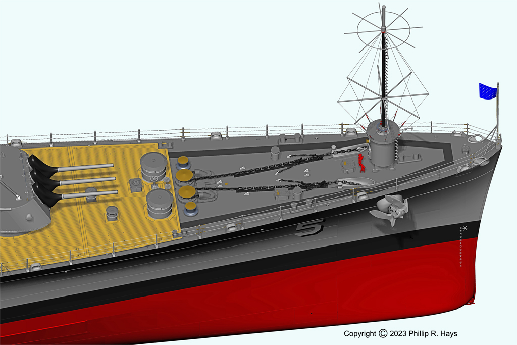
The ship had two anchors on the bow. Each was connected to an anchor chain that led back around a wildcat and then down into a chain pipe that connected to the chain locker near the bottom of the ship. The wildcat was a large chain sprocket that was powered by a hydraulic transmission to raise and lower the anchor. The wildcat also had a brake that could be set to hold the chain and prevent it from paying out.
Except when lowering or raising the anchors each chain was secured in place with "chain stoppers," short lengths of smaller chain with turnbuckles that were fastened to the deck and had pelican hooks that fit around the anchor chain. After the stoppers were clamped around the anchor chain and the tension was taken up with the turnbuckles the wildcat brakes were released. Then the stoppers supported the weight of the anchors. There were two stoppers on each anchor chain.
Each anchor weighed 13,000 pounds. It was assumed that the anchor gear might have to lift 60 fathoms of chain from the bottom, and that would weigh 22,500 pounds, and there would be 40% friction in the hawse pipe, or 14,200 pounds. The total weight that would need to be lifted was 49,700 pounds.
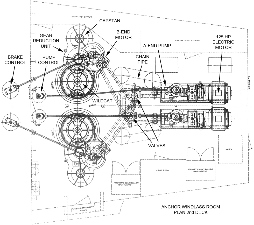
The control stands for the anchor equipment were on the main deck just aft of the wildcats. Duplicate controls in the Anchor Windlass Room on the second deck allowed the equipment to be operated from there if necessary.
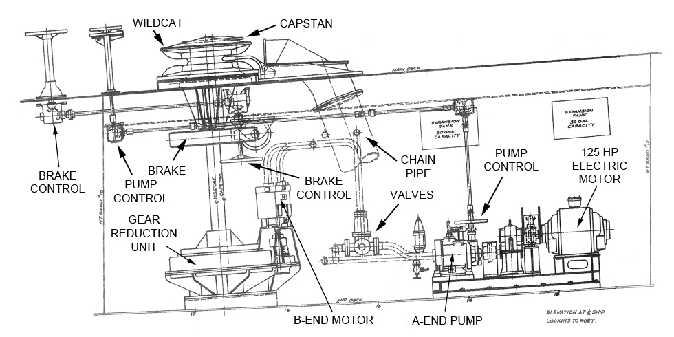
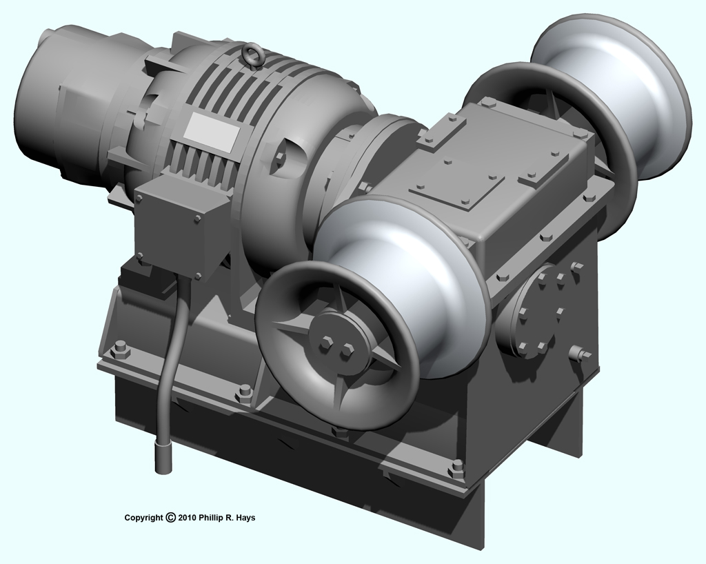
There were two separate systems, port and starboard, with the hydraulic equipment in the Anchor Windlass Room. Piping from the hydraulic pumps ran to a set of valves that allowed either pump to drive either hydraulic motor. The B-end motors drove a gear reduction unit that powered the wildcat and a capstan just outboard of the wildcat. The capstan was used to take in or let out mooring lines and towing cables.
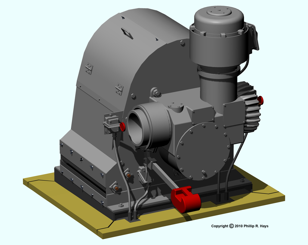
Winches
The ship had a variety of winches, each for a specific task. The smallest were the topping winches. The ship had two of these on the aft end of the missile house top, port and starboard. They were powered by an electric motor and gear drive, and were used for hauling on lines to move heavy equipment around on top of the missile house. They were controlled from switches located nearby on the superstructure.
These winches had dual capstans for working with ropes. They were used to pull lines for moving the heavy mobile cradles for the Seventh Fleet staff boat and the Admiral's barge into position so the boats could be placed into the water, and then back again to the stowage position aft. They also raised and lowered Talos missile warhead containers into position over the warhead strikedown hatches on the aft end of the missile house.
The whaleboat winch raised and lowered the boat davits and the whaleboat when it was launched and recovered. It was located on the starboard side amidships between the whaleboat davits. This winch had an electric motor drive and reduction gears. It had two cable drums to manage the cables that lowered and raised the two boat supports on each of the davit channels. It was operated from controls located on the winch.
The topping winches were also powered by electric motors and gear drives. They raised and lowered the boat booms on the kingposts. The boat booms were used to lift boats and other heavy objects. The topping winches raised the booms out of their storage cradles and into the working positions, and lowered them back again. Two of these winches were located on the 03 level just forward of the missile house between the kingposts. They were controlled by switches nearby on the superstructure.
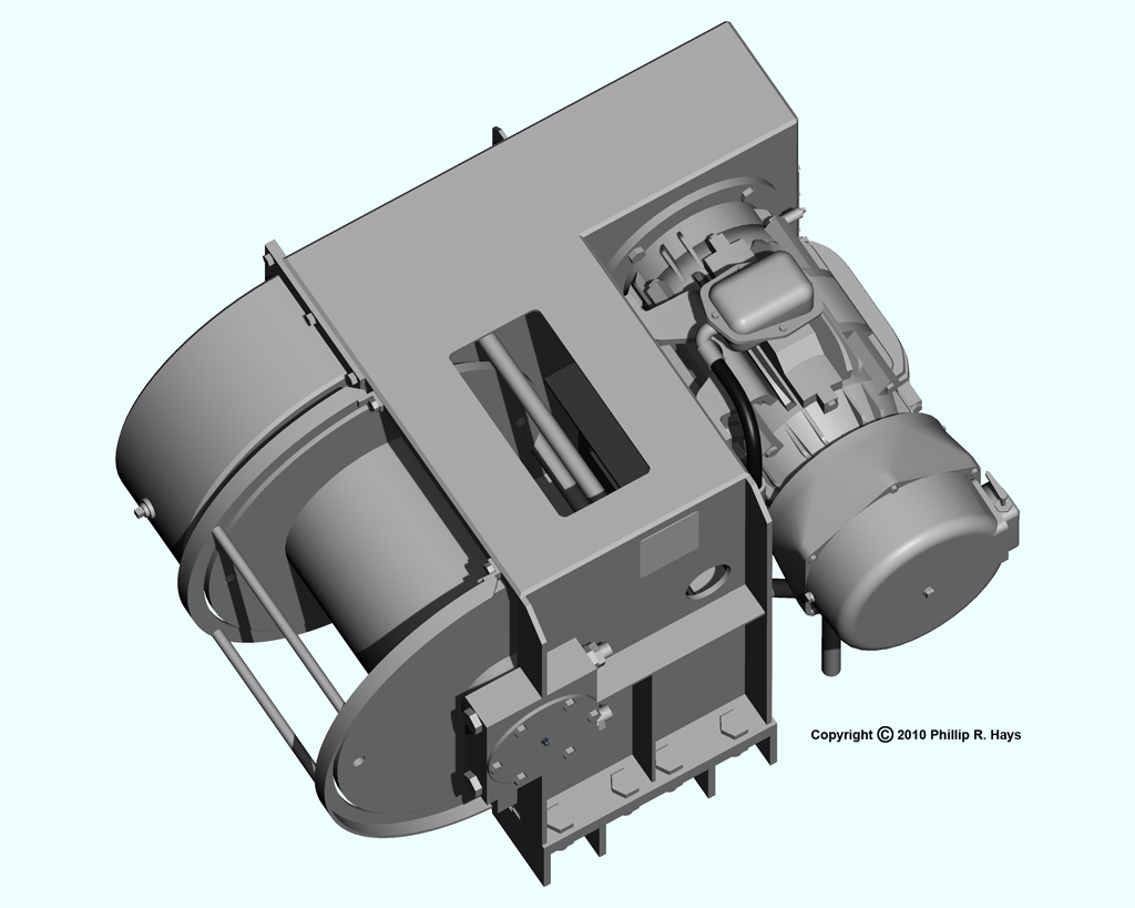
Boat winches were large units with electrohydraulic drives. These winches operated the cables on the boat booms that lifted the ship's boats from their cradles and lowered them into the water, and just the reverse when the boats were being recovered. These winches, the topping winches and the boat booms were also used to lift the Seventh Fleet staff boat and the Admiral's barge to their mobile cradles on the top of the missile house. Occasionally they were used to raise other heavy objects, like automobiles, onto the ship. The ship had two boat winches located port and starboard beneath the boat decks. These were operated from winch control stands on the 03 level just aft of the kingposts.
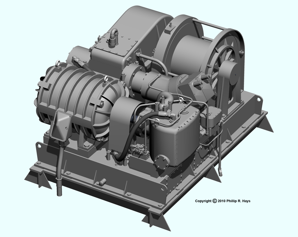
The burtoning winch was the largest winch on the ship. It had a powerful electrohydraulic drive and a reduction gear to generate a large torque to drive the cable drum. This was the heavy lift winch used for ship-to-ship underway replenishment. It pulled a cable that ran through blocks on the FAST crane kingpost on the forward end of the missile house top. This cable was attached to the transfer cable from the replenishment ship, and was operated in conjunction with the winches on the replenishment ship. The replenishment ship controlled movement of supplies to the OK City. When the transfer load was in position over the missile house the burtoning winch lowered the objects to the missile house deck. The winch was located on the 03 level between the topping winches. It was operated from a control stand on the 03 level.
The cable from this winch could also be run through blocks attached to the after superstructure for general purpose uses where a strong pull was needed.
References
1. Principles of Naval Engineering, NAVPERS 10788-B, Bureau of Naval Personnel,1970.2. Blueprints for the original Cleveland class ships and for the CLG Talos modifications.